CWM(L)
advertisement

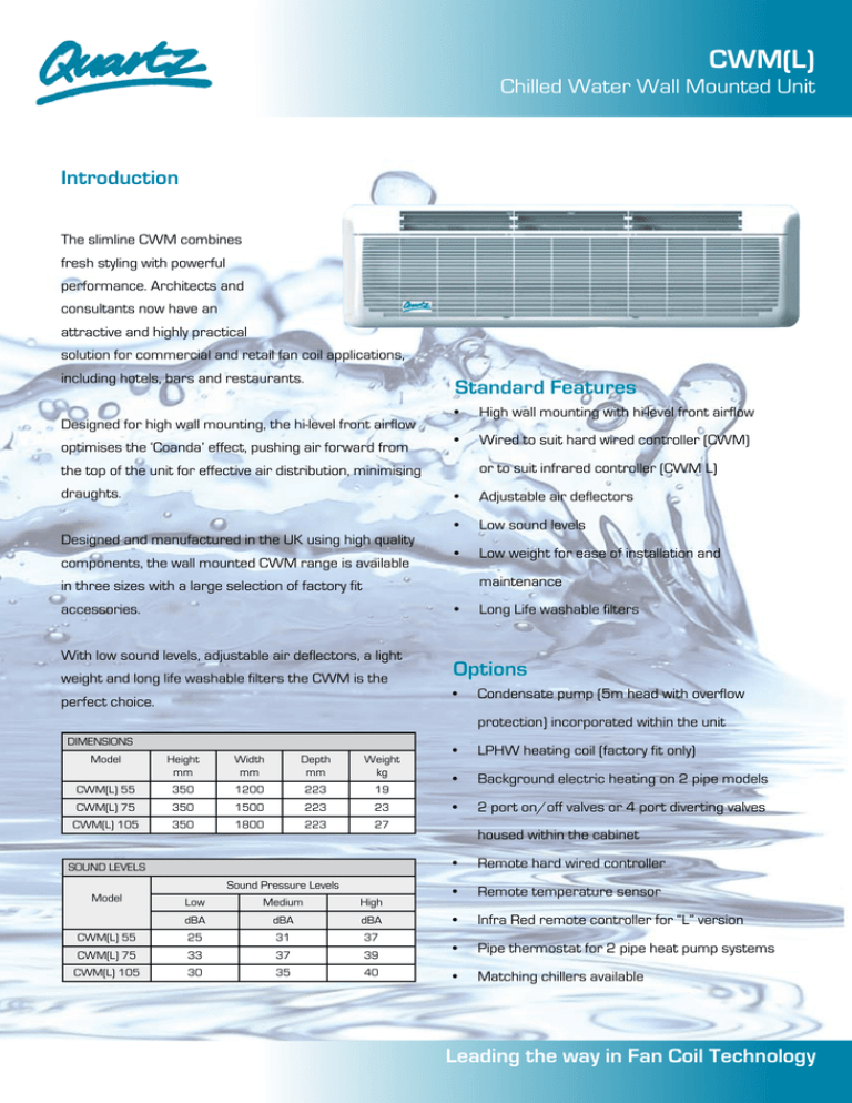
CWM(L) Chilled Water Wall Mounted Unit Introduction The slimline CWM combines fresh styling with powerful performance. Architects and consultants now have an attractive and highly practical solution for commercial and retail fan coil applications, including hotels, bars and restaurants. Standard Features Designed for high wall mounting, the hi-level front airflow optimises the ‘Coanda’ effect, pushing air forward from • High wall mounting with hi-level front airflow • Wired to suit hard wired controller (CWM) or to suit infrared controller (CWM L) the top of the unit for effective air distribution, minimising draughts. Designed and manufactured in the UK using high quality components, the wall mounted CWM range is available • Adjustable air deflectors • Low sound levels • Low weight for ease of installation and maintenance in three sizes with a large selection of factory fit accessories. • With low sound levels, adjustable air deflectors, a light weight and long life washable filters the CWM is the perfect choice. Long Life washable filters Options • Condensate pump (5m head with overflow protection) incorporated within the unit DIMENSIONS Model Height mm Width mm Depth mm Weight kg CWM(L) 55 350 1200 223 19 CWM(L) 75 350 1500 223 23 CWM(L) 105 350 1800 223 27 SOUND LEVELS Sound Pressure Levels Model • LPHW heating coil (factory fit only) • Background electric heating on 2 pipe models • 2 port on/off valves or 4 port diverting valves housed within the cabinet • Remote hard wired controller • Remote temperature sensor • Infra Red remote controller for “L” version Low Medium High dBA dBA dBA CWM(L) 55 25 31 37 CWM(L) 75 33 37 39 • Pipe thermostat for 2 pipe heat pump systems CWM(L) 105 30 35 40 • Matching chillers available Leading the way in Fan Coil Technology Technical Data Cooling Capacities - 2 Pipe – kW Eurovent conditions shown in BOLD Air entry dry bulb (wet bulb) Model 27°C (19°C) 23°C (16°C) Fan Speed Fan Speed Water CWM55 In °C Out °C 6 12 7 CWM75 12 6 12 7 CWM105 12 6 12 7 Heating Capacities 1 12 2 3 1 2 3 TC 2.51 271 3.35 1.75 1.86 2.28 SC 2.13 2.33 2.89 1.60 1.71 2.10 TC 2.55 2.81 3.54 1.71 1.84 2.24 SC 2.20 2.41 3.05 1.57 1.70 2.06 TC 3.96 4.81 5.35 2.68 3.06 3.32 SC 3.28 3.99 4.49 2.44 2.78 3.03 TC 4.12 5.09 5.72 2.62 3.11 3.43 SC 3.42 4.22 4.75 2.41 2.86 3.16 TC 4.95 6.19 8.15 3.11 3.72 4.76 SC 3.96 4.95 6.44 2.80 3.38 4.33 TC 5.11 6.36 8.25 3.13 3.85 5.01 SC 4.09 5.09 6.60 2.85 3.50 4.56 Eurovent conditions shown in BOLD Air entry dry bulb 20°C db Fan Speed Model Water In °C CWM 55 CWM 75 CWM105 1 Out °C 2 3 82 71 1.05 1.25 1.55 70 60 0.55 0.55 0.65 60 50 0.39 0.40 0.35 82 71 1.94 2.14 2.34 70 60 1.24 1.54 1.74 0.54 60 50 0.44 0.54 82 71 2.33 2.63 3.03 70 60 1.73 2.03 2.33 60 50 0.63 0.73 0.93 REVERSE CYCLE CHILLER HEATING DUTIES - TWO PIPE SYSTEM Eurovent conditions shown in BOLD Model CWM(L) Air Entering Dry Bulb 18°C 20°C 22°C Fan Speed Fan Speed Fan Speed Water in °C * Low Medium High Low Medium High Low Medium High 55 50 4.79 5.20 6.28 4.48 4.86 5.88 4.16 4.52 5.46 75 50 6.78 8.02 8.80 6.34 7.50 8.23 5.89 6.97 7.65 105 50 7.79 9.32 11.41 7.28 8.71 10.67 6.76 8.09 9.91 * Flow rate as per cooling AIRFLOWS OPTIONAL ELECTRICAL HEATING (2 pipe models only) Airflows Model Low Medium High m 3/s m 3/s m 3/s CWM(L) 55 0.190 0.210 0.265 CWM(L) 75 0.23 0.31 0.37 CWM(L) 105 0.23 0.34 0.43 Model At 230V kW CWM(L) 55 1.2 1.2 CWM(L) 75 1.7 1.8 CWM(L) 105 2.1 2.3 Approved to BS EN ISO 14001:2004 Approved to BS EN ISO 9001:2000 Certificate No. EMS 91502 Certificate No. FM 671 At 240V kW TEV Ltd For full design information, reference should be made to the technical manual. We reserve the right to alter designs and specifications at any time without notification. Part No: 06617623-03 TEV Ltd, Quartz Division, Armytage Road, Brighouse, West Yorkshire, HD6 1QF, England. Tel: +44 (0) 1484 405630 Fax : +44 (0) 870 606 4876 E: sales@quartz.co.uk W: www.quartz.co.uk FAN COILS : CHILLED WATER CASSETTES : CHILLED BEAM : CHILLERS


