ES 272 Assignment #1
advertisement

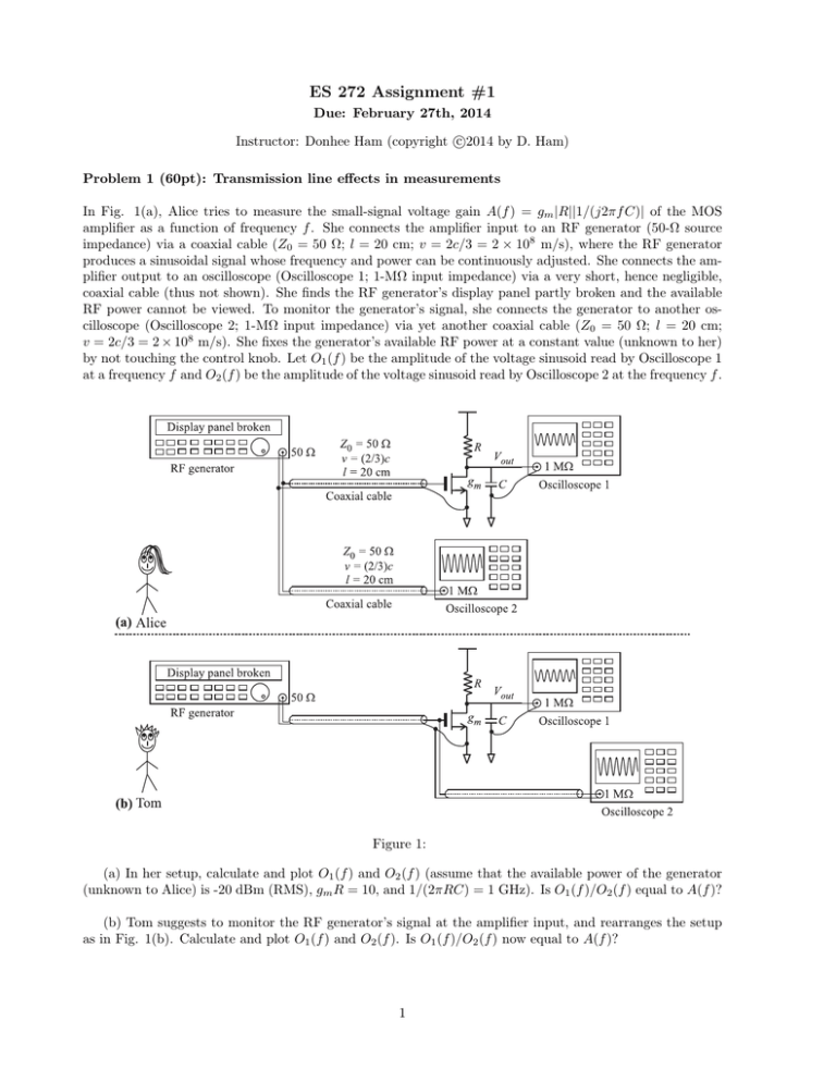
ES 272 Assignment #1 Due: February 27th, 2014 c Instructor: Donhee Ham (copyright 2014 by D. Ham) Problem 1 (60pt): Transmission line effects in measurements In Fig. 1(a), Alice tries to measure the small-signal voltage gain A(f ) = gm |R||1/(j2πf C)| of the MOS amplifier as a function of frequency f . She connects the amplifier input to an RF generator (50-Ω source impedance) via a coaxial cable (Z0 = 50 Ω; l = 20 cm; v = 2c/3 = 2 × 10⁸ m/s), where the RF generator produces a sinusoidal signal whose frequency and power can be continuously adjusted. She connects the amplifier output to an oscilloscope (Oscilloscope 1; 1-MΩ input impedance) via a very short, hence negligible, coaxial cable (thus not shown). She finds the RF generator’s display panel partly broken and the available RF power cannot be viewed. To monitor the generator’s signal, she connects the generator to another oscilloscope (Oscilloscope 2; 1-MΩ input impedance) via yet another coaxial cable (Z0 = 50 Ω; l = 20 cm; v = 2c/3 = 2 × 10⁸ m/s). She fixes the generator’s available RF power at a constant value (unknown to her) by not touching the control knob. Let O1 (f ) be the amplitude of the voltage sinusoid read by Oscilloscope 1 at a frequency f and O2 (f ) be the amplitude of the voltage sinusoid read by Oscilloscope 2 at the frequency f . Figure 1: (a) In her setup, calculate and plot O1 (f ) and O2 (f ) (assume that the available power of the generator (unknown to Alice) is -20 dBm (RMS), gm R = 10, and 1/(2πRC) = 1 GHz). Is O1 (f )/O2 (f ) equal to A(f )? (b) Tom suggests to monitor the RF generator’s signal at the amplifier input, and rearranges the setup as in Fig. 1(b). Calculate and plot O1 (f ) and O2 (f ). Is O1 (f )/O2 (f ) now equal to A(f )? 1 Problem 2 (50pt): Quarter wavelength matching When two transmission lines are to be connected in cascade, a reflection of the wave to be transmitted from one to the other will occur if they do not have the same characteristic impedances. In this problem we will show that a line inserted between the cascaded lines, whose legnth is λ/4, (λ: the design wavelength in the inserted line), will cause the first line to p see its own characteristic impedance Z0,1 as a termination and thus eliminate reflection in transfer if Z0,2 = Z0,1 Z0,3 , where Z0,2 and Z0,3 are the characteristic impedances of the inserted section and the final line, respectively. See Fig. 2. We assume that the final line is infinitely long. (a) Single reflection viewpoint: Show that the “overall” reflection coefficient, ρ, of a wave incident on the boundary 1 is expressed as ρ= 2 Z0,2 − Z0,1 Z0,3 2 Z0,2 + Z0,1 Z0,3 (1) by evaluating the effective load impedance, Zin , looking to the right on boundary 1 (See Fig. 2.), and using the p formula for the reflection coefficient, ρ = (Zin − Z0,1 )/(Zin + Z0,1 ). Equation (1) shows that for Z0,2 = Z0,1 Z0,3 , there is no reflection and impedance matching is achieved. Figure 2: Quarter wavelength matching. (b) Multiple reflection viewpoint: In Fig. 2, imagine a wave traveling down the 1st line towards the 2nd line. When the wave first hits boundary 1 with the 2nd line, it sees only impedance Z0,2 since it has not yet traveled to the 3rd line and can’t see that effect. Part of the wave is reflected with a coefficient ρ1 , and the rest is transmitted onto the 2nd line with a coefficient τ1 . The transmitted wave then travels λ/4 in the 2nd line towards the 3rd line, is reflected with a coefficient ρ3 , and travels another λ/4 back to boundary 1. Part of this wave is transmitted through to the 1st line, with a coefficient τ2 , and the rest is reflected back towards the 3rd line with a coefficient ρ2 . We summarize these “local” reflection and transmission coefficients as follows: • ρ1 : “local” reflection coefficient of a wave incident on the 2nd line from the 1st line. • ρ2 : “local” reflection coefficient of a wave incident on the 1st line from the 2nd line. 2 • ρ3 : “local” reflection coefficient of a wave incident on the 3rd line from the 2nd line. • τ1 : “local” transmission coefficient of a wave incident from the 1st line into the 2nd line. • τ2 : “local” transmission coefficient of a wave incident from the 2nd line into the 1st line. Express ρ1 , ρ2 , ρ3 , τ1 , and τ2 in terms of Z0,1 , Z0,2 , and Z0,3 . The multiple reflection and transmission process continues with an infinite number of bouncing waves, and the “overall” reflection coefficient, ρ, at boundary 1, which we have calculated in (a), can be thought of as the sum of all of the partial reflections. Noting that each round trip path up and down the 2nd line results in a 180 degree phase shift (explain why), demonstrate that the overall reflection coefficient can be expressed as ρ= ρ1 + ρ1 ρ2 ρ3 − τ1 τ2 ρ3 1 + ρ2 ρ3 (2) Show that (2) is equivalent to (1). Problem 3 (50pt): Lossy transmission line A lossy transmission line can be modeled using an LRCG ladder network, and the propagation constant, γ = α + jβ, and the characteristic impedance, Z0,lossy , of the line are given by p (R + jωL)(G + jωC) (3) γ = s jωL + R Z0,lossy = (4) jωC + G where L, R, C, and G signify inductance, series resistance, capacitance, and shunt conductance per unit length, respectively. It is quite straightforward to derive these expressions by extending the method discussed in Lecture #1 (although this derivation is not the part of this problem, I encourage you to derive these expressions). The goal of this problem is to calculate the quality factor, Q, of the lossy line. In what follows, we will assume that the losses, R and G, are small enough to satisfy |jωL| R and |jωC| G; we will neglect second- and higher-order terms of R/|jωL| and G/|jωC| as well as their cross-product terms (small-loss approximation). (a) Show that the propagation constant of the lossy transmission line can be approximated as γ = α + jβ ≈ 1 R G ω ( + )+j 2v0 L C v0 (5) √ in the small-loss approximation, where v0 ≡ 1/ LC is the phase velocity in the lossless case. (b) Show that the characteristic impedance of the lossy transmission line can be approximated as Z0,lossy ≈ Z0 ejφ0 (6) p in the small-loss approximation, where Z0 ≡ L/C is the characteristic impedance in the lossless case, and φ0 is approximately given by φ0 ≈ 1/(2ω) · (G/C − R/L). (c) As shown in Fig. 3, an infinitely long, lossy transmission line is driven by a sinusoidal source at z = 0 and as a result, the voltage in the transmission line at z = 0 is given by V0 cos(ωt). Using the phasor, e−γz+jωt , and relevant boundary conditions, show that the voltage and current at point z in time t are given by V (z, t) = I(z, t) ≈ V0 e−αz cos(βz − ωt), V0 −αz e cos(βz − ωt + φ0 ). Z0 (7) (8) Using these results, show that the total time-averaged energy stored in the transmission line segment between z = 0 and z = l is given by 1 1 − e−2αl Etot = CV02 · . (9) 2 2α 3 l 0 z V0 cos wt Figure 3: Q of a lossy transmission line. Also show that the total time-averaged power dissipation in the same line segment is given by Pdiss = 1 R 1 − e−2αl ( 2 + G)V02 · . 2 Z0 2α (10) (d) Using the results above, show that the Q of the lossy transmission line is given by Q= β ωLC = . RC + GL 2α (11) (Problem 4) Artificial transmission line (40pt) The artificial transmission line is a lattice of “lumped” LC sections [Fig. 4(a)]; note that here L and C are not per-unit-length quantities; i.e., they do have the unit of inductance and capacitance. Differently from the transmission line, the artificial transmission line, even in the lossless case, possesses a cutoff frequency and a frequency-dependent characteristic impedance due to its lumped periodicity (non-smoothness). In this problem, we derive these properties of the artificial line. Figure 4: Artificial transmission line (a) The input impedance of an infinitely long artificial line [Fig. 4(a)] is its characteristic impedance. This impedance is also called image impedance, Zimage . Show that Zimage is given by s ω2 Zimage = Z0 · 1 − 2 (12) ωc p √ where Z0 ≡ L/C and ωc ≡ 2/ LC. You can solve this problem by noticing that adding another LC section at the beginning of the artificial line would not change the image impedance. What happens to 4 Zimage at angular frequencies in excess of ωc ? (b) From the definition of Zimage , we know that Zimage provides a perfect termination (no reflection) to an artificial transmission line, and the infinitely long artificial line [Fig. 4(a)] is equivalent to a finite artificial line terminated with Zimage [Fig. 4(b)]. Using this notion, show that an input impedance, Zmiddle , seen at an arbitrary node in an artificial line infinitely long in both directions [Fig. 4(c)] is given by Zmiddle = 1 Z0 . ·p 2 1 − ω 2 /ωc2 (13) What happens to Zmiddle at angular frequencies in excess of ωc ? (c) Any sinusoidal signal whose angular frequency is larger than ωc cannot be propagated on the artificial line (hence the name, cutoff frequency, for ωc ). To prove this, first show that the wave equation in the artificial line is given by the following equation LC d2 Vn (t) = Vn−1 (t) − 2Vn (t) + Vn+1 (t) dt2 (14) where Vn (t) is the voltage across the n-th capacitor at time t. For a sinusoidal wave, Vn (t) can be written as Vn (t) = A0 · ej(ωt−βn) (15) where A0 is the amplitude, ω is the angular frequency, and β is the wave number1 . By substituting (15) into the wave equation of (14), show that ω and β are related through β ω = ωc sin . (16) 2 This ω-β relation indicates that the velocity2 v = ω/β is a function of frequency ω, that is, different frequency components travel at different speeds. This “dispersion” phenomenon is another characteristic of the artificial line. Using the ω-β dispersion relation, show that any sinusoidal wave whose angular frequency is in excess of ωc cannot be propagated down the artificial line. (Problem 5) Time-domain reflectometry (TDR) — “transmission line radar” (50pt) Time-domain reflectometry (TDR) is a tool to characterize discontinuities (or defects) in transmission lines. In the presence of a discontinuity in a transmission line, a step pulse launched onto the line will be reflected at the discontinuity location and an “echo” signal will be returned. The arrival time and shape of the echo provides information on the location and nature of the discontinuity. The TDR may be viewed as radar operating on a transmission line. This problem asks you to calculate responses of transmission lines with a variety discontinuities to a step pulse excitation. (a) Transmission line with a termination Figure 5(a) shows a transmission line with a resistive termination. A step voltage pulse (step size: V0 ) is launched onto the transmission line at z = 0 and at time t = t1 and the response is measured at the same location z = 0. A reflection will occur at the termination z = l after a time elapse of l/v where l is the line length and v is the wave velocity. The reflection will arrive at z = 0 after an additional time elapse of l/v. Figure 5(b) shows the voltage signal at z = 0 versus time t in the case of R = ∞ (open termination). V (z = 0, t) during t1 < t < t2 = t1 + 2l/v corresponds to the input voltage step pulse. V (z = 0, t) for t > t2 corresponds to the superposition of the input step pulse and the reflected signal. Plot V (z = 0, t) versus t (step voltage V0 input at t = t1 ) like Figure 5(b) for the following cases: 1 While in the continuous transmission line, β/(2π) in the unit of [1/length] signifies how many wavelengths a unit length contains, in the artificial line, β/(2π) is unitless, and signifies how many wavelengths a unit lattice (∆n = 1) contains. 2 This velocity in the artificial line, in the unit of [1/time], is the number of lattices the wave’s phase passes per unit time. 5 Figure 5: Time-domain reflectometry (TDR) • • • • • R = 0; Figure 5(a) R < Z0 ; Figure 5(a) R > Z0 ; Figure 5(a) Capacitive termination; Figure 5(c) Inductive termination; Figure 5(d) (b) Transmission line with a discontinuity Assume again that a step voltage pulse (step size: V0 ) is launched onto the transmission line at z = 0 and at time t = t1 . Plot V (z = 0, t) versus t for the following cases, where the transmission line is not terminated, but has a discontinuity (defect): • Shunt capacitive discontinuity: Figure 5(e) • Series capacitive discontinuity: Figure 5(f) 6 (Problem 6) Examples of more complex microwave passive circuits (100pt) (a) Consider a microstrip structure of Fig. 6. The ground plane, which is not shown, is located below the microstrip structure (a dielectric is sandwiched between the microstrip structure and ground plane). There are four ports, 1, 2, 3, and 4, which are shown as circled numbers in the figure. A signal generator with an output impedance of Z0 is connected to Port 1 where a sinusoidal signal is entered. The frequency of the signal is so chosen that the quarter wavelength is equal to each side of the square shape in the middle of the microstrip structure. All other ports are also matched to impedance Z0 . How are the phase and amplitude of the output signals at Ports 2, 3, and 4 are related to the phase and amplitude of the input signal at Port 1? Z0/Ö2 Z0 Z0 1 2 ë/4 Z0 Z0 ë/4 4 3 Z0 Z0/Ö2 Z0 Figure 6: Microstrip network (b) Consider another microstrip structure with four ports, 1, 2, 3, and 4, shown in Fig. 7. All ports are matched to impedance Z0 . If a sinusoidal signal (its frequency is so chosen that the wavelength is as shown in the figure) is applied to Port 1, how are the amplitude and phase of the output signals at Ports 2, 3, and 4 are related to the amplitude and phase of the input signal at Port 1? If the sinusoidal signal is applied to Port 4, how are the amplitude and phase of the output signals at Ports 1, 2, and 3 are related to the amplitude and phase of the input signal at Port 4? Prove that with input signals applied at Ports 2 and 3, the sum of the inputs will appear at Port 1 and the difference will appear at Port 4. 2 ë/4 1 Ö2 Z0 ë/4 3 3ë/4 ë/4 4 Figure 7: Microstrip network 7 [Suggested reading on on-chip transmission line resonators and NMR RF electronics] [1] William Andress and Donhee Ham, “Standing wave oscillators utilizing wave-adaptive tapered transmission lines,” IEEE Journal of Solid-State Circuits 40, 638 (2005). [2] Nan Sun, Tae-Jong Yoon, Hakho Lee, Willliam Andress, Ralph Weissleder, and Donhee Ham, “Palm NMR and 1-chip NMR,” IEEE Journal of Solid-State Circuits 46 , 342 (2011) [3] Nan Sun, Yong Liu, Hakho Lee, Ralph Weissleder, and Donhee Ham, “CMOS RF biosensor utilizing nuclear magnetic resonance,” IEEE Journal of Solid-State Circuits 44, 1629 (2009). 8


