An introduction to Junction Field Effect Transistors (JFETs)
advertisement

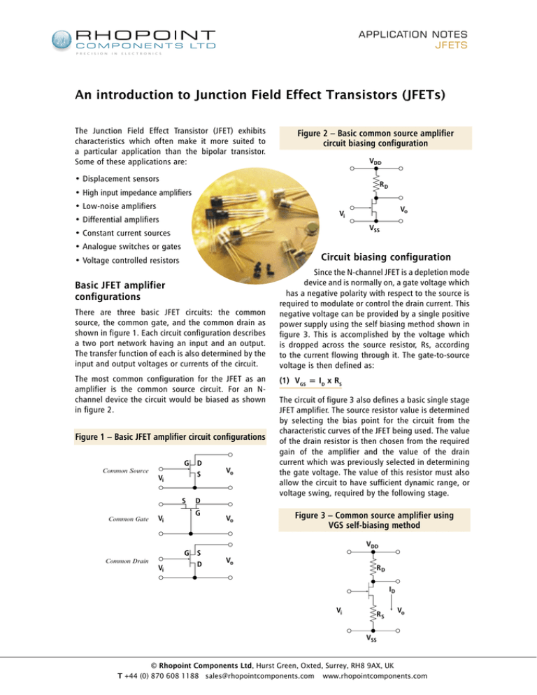
APPLICATION NOTES JFETS P R E C I S I O N I N E L E C T R O N I C S An introduction to Junction Field Effect Transistors (JFETs) The Junction Field Effect Transistor (JFET) exhibits characteristics which often make it more suited to a particular application than the bipolar transistor. Some of these applications are: Figure 2 – Basic common source amplifier circuit biasing configuration VDD • Displacement sensors RD • High input impedance amplifiers • Low-noise amplifiers VSS • Constant current sources • Analogue switches or gates Circuit biasing configuration • Voltage controlled resistors Basic JFET amplifier configurations There are three basic JFET circuits: the common source, the common gate, and the common drain as shown in figure 1. Each circuit configuration describes a two port network having an input and an output. The transfer function of each is also determined by the input and output voltages or currents of the circuit. The most common configuration for the JFET as an amplifier is the common source circuit. For an Nchannel device the circuit would be biased as shown in figure 2. Figure 1 – Basic JFET amplifier circuit configurations Common Source G D S Vi S Common Gate Vi Vi Vo D G G S Common Drain Vo Vi • Differential amplifiers D Vo Since the N-channel JFET is a depletion mode device and is normally on, a gate voltage which has a negative polarity with respect to the source is required to modulate or control the drain current. This negative voltage can be provided by a single positive power supply using the self biasing method shown in figure 3. This is accomplished by the voltage which is dropped across the source resistor, Rs, according to the current flowing through it. The gate-to-source voltage is then defined as: (1) VGS = ID x RS The circuit of figure 3 also defines a basic single stage JFET amplifier. The source resistor value is determined by selecting the bias point for the circuit from the characteristic curves of the JFET being used. The value of the drain resistor is then chosen from the required gain of the amplifier and the value of the drain current which was previously selected in determining the gate voltage. The value of this resistor must also allow the circuit to have sufficient dynamic range, or voltage swing, required by the following stage. Figure 3 – Common source amplifier using VGS self-biasing method VDD Vo RD ID Vi RS Vo VSS © Rhopoint Components Ltd, Hurst Green, Oxted, Surrey, RH8 9AX, UK T +44 (0) 870 608 1188 sales@rhopointcomponents.com www.rhopointcomponents.com APPLICATION NOTES JFETS P R E C I S I O N I N E L E C T R O N I C S An introduction to Junction Field Effect Transistors (JFETs) The following stage could be anything from another identical circuit to a loud speaker for an audio system. The voltage gain of this circuit is then defined as: Figure 4 – Low noise JFET single stage amplifier with source by-pass capacitor, CS VDD (2) AV = ( gm x Zl ) / ( 1 + gm x R S ) where A V = the voltage gain g m = the forward transconductance or gain of the JFET Zl = the equivalent load impedance R S = the value of the source resistor RD Vo Vi RG The effect of the source resistor on the gain of the circuit can be removed at higher frequencies by connecting a capacitor across the source resistor. This then results in an amplifier which has a gain of: (3) A V = g m x Z l but only at frequencies above that defined by the resistor-capacitor network in the source circuit. cont. RS CS VSS These noise characteristics are generally lower than those found in bipolar transistors if the JFET is properly selected for the application. The voltage gain of the circuit is again defined by equation (3). This frequency is defined as: (4) f lo = 1 / (2π x R S x C S ) where ohms farads flo = the low frequency corner π = the constant 3.1418 RS = the value of the source resistor in Figure 5 – The matched pair JFET differential amplifier VDD CS = the value of the source capacitor in This circuit also has a high input impedance, generally equal to the value of the input impedance of the JFET. A low-noise amplifier A minor change to the circuit of figure 3 describes a basic single stage low-noise JFET amplifier. Figure 4 shows that this change only incorporates a resistor from the gate to Vss. This resistor supplies a path for the gate leakage current in an AC coupled circuit. Its value is chosen by the required input impedance of the amplifier and its desired low-noise characteristics. The noise components of this amplifier are the thermal noise of the drain and gate resistors plus the noise components of the JFET. The noise contribution of the JFET is from the shot noise of the gate leakage current, the thermal noise of the channel resistance, and the frequency noise of the channel. RD RD Vo – Vi + Vi RS VSS The JFET differential amplifier Another application of the JFET is the differential amplifier. This configuration is shown in figure 5. The differential amplifier requires that the two transistors be closely matched electrically and physically located near each other for thermal stability. Either input and either output can be used or both inputs and only one output and conversely only one input and both outputs can be used. © Rhopoint Components Ltd, Hurst Green, Oxted, Surrey, RH8 9AX, UK T +44 (0) 870 608 1188 sales@rhopointcomponents.com www.rhopointcomponents.com APPLICATION NOTES JFETS P R E C I S I O N I N E L E C T R O N I C S An introduction to Junction Field Effect Transistors (JFETs) Figure 6 – JFET constant current source G ID D S RS VSS For the configuration shown the source resistor is chosen to determine the gate to source bias voltage, remembering that the current will be twice that of each of the JFET drain currents. The value of the drain resistors is chosen to provide a suitable dynamic range at the output. The gain of this circuit is defined by: (5) A V = 2x (g m x R l ) / (1 + g m x R S ) The JFET analogue switch Figures 7, 8, and 9 show three different applications for the JFET to be used as an analogue switch or gate. Figures 7 and 8 both demonstrate methods for realising programmable gain amplifiers, while figure 9 shows an analogue multiplexer circuit using JFETs and a common op-amp integrated circuit. It can be seen from figure 7 that the gain of the stage can be changed by switching in any combination of feedback resistors R1 through Rn. The JFET in series with the input resistor should be of the same type as those in the feedback paths and is used for thermal stability of the circuit gain. The transfer function of the circuit of figure 7 is approximated by: (7) Vo / Vi = 1 / [ (1 / R1) + (1 / R2) + .... + (1 / R n) ] / Ri where R1 through Rn Ri Vo Vi where the terms in the equation have already been defined. This circuit configuration is very useful as a high input impedance stage to be connected to the input of a low cost operational amplifier, such as the popular 741 Op-Amp. The JFET constant current source A constant current source using a JFET is shown in figure 6. This circuit configuration has many useful applications ranging from charging circuits for integrators or timers to replacing the source resistor in the differential amplifier shown in figure 5. The current provided by the constant current source of figure 6 is defined as: (6) ID = I DSS [ 1 - (VGS / Vp ) ] where ID IDSS VGS Vp 2 2 = the drain current or magnitude of current sourced = the drain saturation current of the JFET = ID x RS = the JFET pinch-off voltage = the squared value of the term in brackets It can be readily seen that the use of this circuit in the source circuit of the differential amplifier of figure 5 would improve the circuit voltage gain as well as reduce the amplifier noise and enhance the CMRR of the amplifier. cont. = the = the = the = the feedback resistors input resistors output voltage input voltage Note that only those feedback resistors which are switched into the circuit are to be included in the the transfer function equation. Figure 7 – Programmable gain amplifier C1 R1 C2 R2 Cn Vi Rl R3 – + Vo The circuit of figure 8 shows another method to realise a programmable gain amplifier using a common op-amp, four resistors, and only two JFETs. The gain of this circuit can also be changed by switching in the desired resistors by turning off the appropriate JFET thus switching in the parallel resistor. The transfer function of this circuit is approximated by: (8) Vo / Vi = (R3 + R4) / (R1 + R2) © Rhopoint Components Ltd, Hurst Green, Oxted, Surrey, RH8 9AX, UK T +44 (0) 870 608 1188 sales@rhopointcomponents.com www.rhopointcomponents.com APPLICATION NOTES JFETS P R E C I S I O N I N E L E C T R O N I C S An introduction to Junction Field Effect Transistors (JFETs) Figure 8 – Programmable gain amplifier with four resistors and two JFETs Figure 9 – Analogue multiplexer circuit which can also be used as a programmable summing amplifier Rf G1 R1 G2 V1 R3 Vi R1 R2 R4 – + Vo R1 G1 R1 G2 V2 VN – + GN It should be noted that only those resistors which are switched into the circuit are to be included in the transfer function equation. Figure 9 shows a circuit in which the JFETs are acting as analogue switches to multiplex several input signal sources to a single output source. The transfer function of this circuit is then approximated by: (9) Vo / Vi = Rf / Rn where cont. Rf = the feedback resistor Rn = any one of the input resistors Further examination of this circuit shows that it can also be used as a programmable summing amplifier by switching in any combination of input signals. The transfer function is then approximated by: (10) Vo / Vi = (Rf / R1) + (Rf / R2) + .... + (Rf / Rn) Again in this application only those resistors which are switched into the circuit are to be included in the transfer function equation. © Rhopoint Components Ltd, Hurst Green, Oxted, Surrey, RH8 9AX, UK T +44 (0) 870 608 1188 sales@rhopointcomponents.com www.rhopointcomponents.com

