PRODUCT DATA
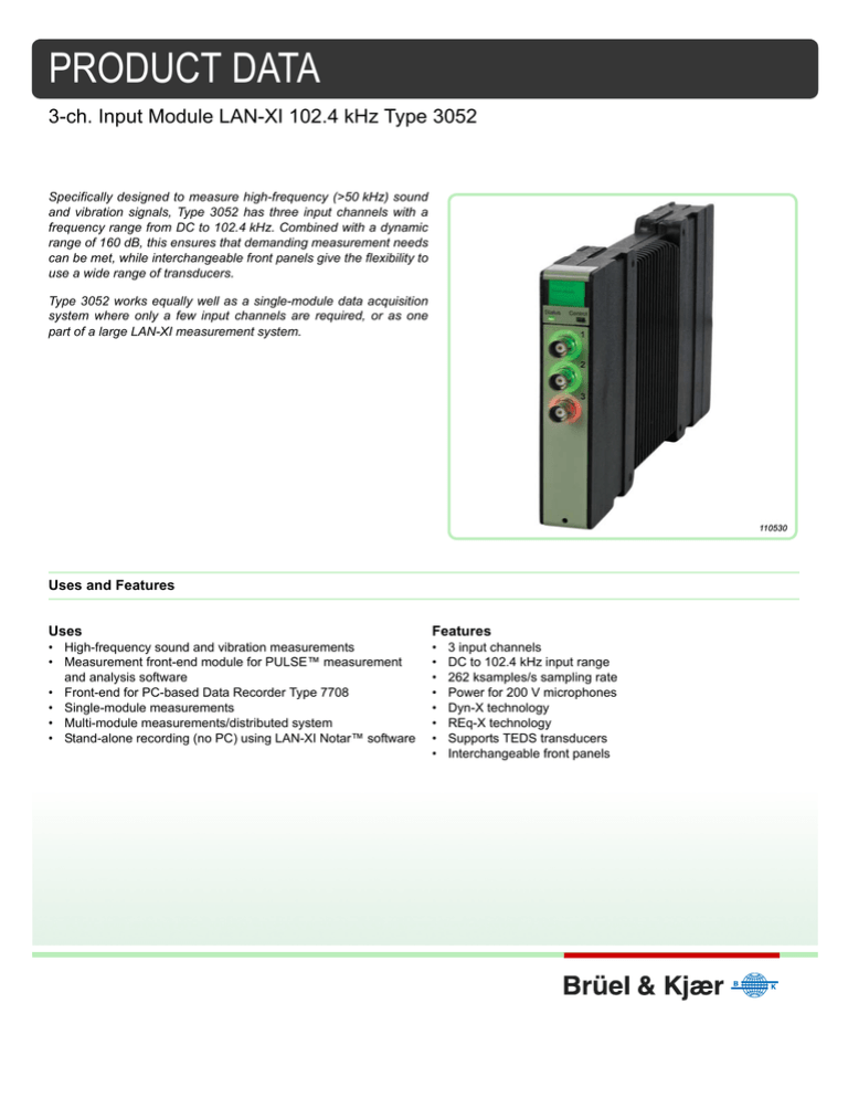
3-ch. Input Module LAN-XI 102.4 kHz Type 3052
Specifically designed to measure high-frequency (>50 kHz) sound
and vibration signals, Type 3052 has three input channels with a
frequency range from DC to 102.4 kHz. Combined with a dynamic
range of 160 dB, this ensures that demanding measurement needs
can be met, while interchangeable front panels give the flexibility to
use a wide range of transducers.
Type 3052 works equally well as a single-module data acquisition
system where only a few input channels are required, or as one
part of a large LAN-XI measurement system.
Uses and Features
Uses
Features
• High-frequency sound and vibration measurements
• Measurement front-end module for PULSE™ measurement
and analysis software
• Front-end for PC-based Data Recorder Type 7708
• Single-module measurements
• Multi-module measurements/distributed system
• Stand-alone recording (no PC) using LAN-XI Notar™ software
•
•
•
•
•
•
•
•
3 input channels
DC to 102.4 kHz input range
262 ksamples/s sampling rate
Power for 200 V microphones
Dyn-X technology
REq-X technology
Supports TEDS transducers
Interchangeable front panels
One Cable Operation
You can use standard LAN cables for synchronous sampling between modules and system power, thanks to
Power over Ethernet (PoE). This minimises the number of cables required and results in lower cost, less
downtime, easier maintenance, and greater flexibility of installation.
Power over Ethernet
PoE is implemented according to IEEE 802.3af. PoE is wired Ethernet LAN technology that, with a suitable
PoE LAN switch, allows the power needed for each module to be carried by screened shielded twisted pair
(S/STP or S/FTP) CAT6 LAN cables rather than by separate power cables. This minimises the number of
cables required and results in lower cost, less downtime, easier maintenance and greater installation
flexibility. PoE switches, such as 10-port Gigabit Managed Switch with PTP and PoE (8 ports) UL-0265, and
PoE Injectors, such as ZyXEL® PoE-12 Power over Ethernet (a single-port PoE injector), can be used.
Built for Field and Lab Use
The modules and the detachable front plates are cast in magnesium for maximum stability, light weight, and
tough field use.
Interchangeable Front Panels
The modules allow front panels to be interchanged freely, with a variety of connectors for different
transducers and applications. This results in fewer patch panels, less cable “spaghetti”, fewer cable adaptors
and faster system setup.
Independent Channels
The input channels on a module can be set up independently. You can set up the high-pass filters and input
gain separately and attach different types of transducer to different channels.
IEEE 1451.4 Transducers
All input modules support TEDS transducers. This allows automatic front-end and analyzer setup based on
TEDS information stored in the transducer, for example, sensitivity, serial number, manufacturer and
calibration date. The individual frequency response of a transducer can be corrected for using PULSE’s
Transducer Response Equalisation, REq-X, to achieve higher accuracy over extended frequency ranges.
Overload
Constant Current Line Drive (CCLD) conditioning monitors the supply voltage used by CCLD-compatible
transducers. Available CCLD transducers include:
• Accelerometers
• Charge amplifiers
• Microphone preamplifiers
• Tacho probes
If conditioning errors, such as a broken cable, are detected, an error is indicated as an overload on the
specific channel connector (using a ring-LED around the connector) and in the PC software.
Overload indications for input channels include (see Specifications for details):
• Signal overload with adjustable detection level
• CCLD overload: detection of cable break, short-circuit or CCLD transducer working point fault
• Microphone preamplifier overload: detection of microphone preamplifier current consumption too high or
too low
• Common mode voltage overload – relevant when input coupling is floating
Ground-loop Noise Suppression
The module’s floating/grounded, differential input design and the fact that all external connections (LAN,
power supply) are galvanically isolated in the module provide optimal ground-loop noise suppression.
2
Compliance with Standards
CE-mark indicates compliance with: EMC Directive and Low Voltage Directive
RCM mark indicates compliance with applicable ACMA technical standards – that is, for telecommunications, radio
communications, EMC and EME
China RoHS mark indicates compliance with administrative measures on the control of pollution caused by electronic
information products according to the Ministry of Information Industries of the People’s Republic of China
WEEE mark indicates compliance with the EU WEEE Directive
Safety
EN/IEC 61010–1 and ANSI/UL 61010–1: Safety requirements for electrical equipment for measurement, control and
laboratory use
EMC Emission
EN/IEC 61000–6–3: Generic emission standard for residential, commercial, and light-industrial environments
CISPR 22: Radio disturbance characteristics of information technology equipment. Class B Limits
EMC Immunity
EN/IEC61000–6–1: Generic standards – Immunity for residential, commercial and light industrial environments
EN/IEC 61000–6–2: Generic standards – Immunity for industrial environments
EN/IEC 61326: Electrical equipment for measurement, control and laboratory use – EMC requirements
Note: The above is only guaranteed using accessories listed in this Product Data
Temperature
IEC 60068−2−1 & IEC 60068−2−2: Environmental Testing. Cold and Dry Heat
Ambient Operating Temperature: −10 to +55°C (14 to 131°F)
Storage Temperature: −25 to +70°C (−13 to +158°F)
Humidity
IEC 60068−2−78: Damp Heat: 93% RH (non-condensing at 40°C (104°F))
Mechanical
(non-operating)
IEC 60068–2–6: Vibration: 0.3 mm, 2 g, 10 – 500 Hz
IEC 60068–2–27: Shock: 100 g
IEC 60068–2–29: Bump: 1000 bumps at 25 g
Enclosure
IEC 60529: Protection provided by enclosures: IP 31
Vibration: 5−500 Hz, 12.7 mm, 15 m/s2
Input measured with shorted input. All values are RMS. Conducted RF
immunity on all channels is only guaranteed using an external connection
from measuring ground to chassis terminal
EFFECT OF RADIATED AND CONDUCTED RF, MAGNETIC FIELD
AND VIBRATION
Radiated RF: 80−2700 MHz, 80% AM 1 kHz, 10 V/m
Conducted RF: 0.15−80 MHz, 80% AM 1 kHz, 10 V
Magnetic Field: 30 A/m, 50 Hz
Radiated RF
Conducted RF
Magnetic Field
Direct/CCLD
Input
<250 μV
<300 μV
<4 μV
Vibration
<80 μV
Preamplifier
<250 μV
<50 μV
<8 μV
<80 μV
Specifications – LAN Interface
CONNECTOR
RJ 45 (10baseT/100baseTX) connector complying with IEEE−802.3
100baseX
Types 3660-C and -D permit the use of a ruggedized RJ45 data
connector (Neutrik NE8MC-1) to screw the cable to the frame
Types 3660-C and -D communicate at 1000 Mbits/s: shielded cables of
type “CAT 5e” or better should be used
Individual modules communicate at 100 Mbits/s
All LAN connectors support MDIX, which means that cables may be
“crossed” or not
For stand-alone modules, PoE is also supported (IEEE 802.3af). PoE
requires screened shielded twisted pair (S/STP or S/FTP) CAT6 LAN
cables
PROTOCOL
The following standard protocols are used:
• TCP
• DHCP (incl. Auto-IP)
• DNS (on top of UDP)
• IEEE 1588–2002 (on top of UDP)
• IP
• Ethernet
ACQUISITION PERFORMANCE
Each LAN-XI module generates data at almost 20 Mbit/s when
measuring three channels at 102.4 kHz bandwidth. The modules are
capable of handling their own maximum traffic while the built-in switch in
the frame’s backplane has more than sufficient capacity. This means that
bottlenecks can only occur outside these, for example in:
• External switches
• PC
For convenience, it is possible to daisy-chain LAN-XI frames. However, it
is not recommended to daisy-chain more than two frames. For larger
configurations, a star configuration with a central switch is recommended.
This must have a switch capacity well beyond N × 20 Mbit/s, where N is
the total number of modules
PTP PERFORMANCE
PTP Synchronisation (with 1 Gigabit LAN Switch):
Typical sample synchronisation better that 200 ns
(approx. ±0.07° @ 1 kHz, ±2° @ 25.6 kHz)
Tested with:
• Cisco® SG300-10MP, 10-port 10/100/1000 Managed Gigabit Switch
with Maximum PoE (8 ports)
• Netgear® 5-port Gigabit Switch GS105
Better performance can be expected with a dedicated PTP switch:
• UL-0265: 10-port Gigabit Managed Switch with PTPv2 and PoE (8
ports).
This is a dedicated PTP switch, preconfigured for optimal use with
LAN-XI
3
Specifications – 3-ch. Input Module LAN-XI 102.4 kHz Type 3052
POWER REQUIREMENTS
DC Input: 10−32 V DC
Connector: LEMO coax., FFA.00.113, ground on shield
Power Consumption:
DC Input: <15 W
Supply via PoE: According to IEEE 802.3af, Max. cable length 50 m
Temperature Protection:
Temperature sensor limits module's internal temperature to 80ºC (176ºF).
If temperature exceeds limit, system will automatically enable fan in
LAN-XI frame or shut down module outside frame
DIMENSIONS AND WEIGHT
Height: 132.6 mm (5.22″)
Width: 27.5 mm (1.08″)
Depth: 250 mm (9.84″)
Weight: 750 g (1.65 lb)
Frequency Range
DC to 102.4 kHz
Lower frequency range can be set in PULSE software
Sampling Rate
262 ksamples/s
A/D Conversion
2 × 24 bit
Data Transfer
24 bit
Input Voltage Range
10 Vpeak
Extended range: 31.6 Vpeak
Differential
Input Signal
Coupling
Signal ground is “floating” (1 MΩ re: chassis)
Single-Ended
Signal ground is connected to chassis (“Grounded”)
Input Impedance
Direct, Microphone: 1 MΩ || <300 pF
CCLD: >100 kΩ || <300 pF
±60 Vpeak without damage
Absolute Maximum Input
High-pass Filters
* Defined as the lower
frequency, fL, for guaranteed
fulfilment of
−0.1 dB accuracy in 10 Vpeak
range
** Defined as the nominal
−10%/3 dB filter frequency
0.1 Hz −10% analog high-pass filter
0.7 Hz −0.1 dB digital high-pass filter
1 Hz −10% digital high-pass filter
7 Hz −0.1 dB digital high-pass filter
22.4 Hz −0.1 dB analog high-pass filter
Intensity filter (analog)
– 0.1 dB *
–10% @ **
–3 dB @ **
Slope
0.5 Hz
0.7 Hz
0.1 Hz
0.15 Hz
0.05 Hz
0.073 Hz
–20 dB/dec.
5 Hz
7 Hz
1.0 Hz
1.45 Hz
0.5 Hz
0.707 Hz
–20 dB/dec.
22.4 Hz
15.8 Hz
12.5Hz
–60 dB/dec.
115Hz
23.00 Hz
11.5 Hz
–20 dB/dec.
Absolute Amplitude Precision, 1 kHz, 1 Vinput
Amplitude Linearity
(linearity in one range)
±0.05 dB, typ. ±0.01 dB
0 to 80 dB below full scale
±0.05 dB, typ. ±0.01 dB
80 to 100 dB below full scale
±0.2 dB, typ. ±0.02 dB
100 to 120 dB below full scale
typ. ±0.02 dB
120 to 140 dB below full scale
typ. ±0.02 dB
140 to 160 dB below full scale
typ. ±1 dB
Overall Frequency Response
re 1 kHz, from lower limit fL to upper limit fU
fL is defined as the lower frequency for guaranteed fulfilment of −0.1 dB accuracy
in 10 Vpeak range (see under High-pass Filters)
fu is defined as the chosen frequency span. DC (fL = 0)
Noise
* Measured lin. 10 Hz to
51.2 kHz or lin. 10 Hz to
102.4 kHz:
(Input terminated by 50 Ω or
less)
Input
Range
Signal level <316 mVpeak
10 Hz to 25.6 kHz
10 Hz to 51.2 kHz
10 Hz to 102.4 kHz
Signal level >316 mVpeak
10 Hz to 25.6 kHz
10 Hz to 51.2 kHz
10 Hz to 102.4 kHz
Signal level <1 Vpeak
10 Hz to 25.6 kHz
10 Hz to 51.2 kHz
10 Hz to 102.4 kHz
Signal level >1Vpeak
10 Hz to 25.6 kHz
10 Hz to 51.2 kHz
10 Hz to 102.4 kHz
4
10 Vpeak
10 Vpeak
31.6 Vpeak
31.6 Vpeak
±0.1 dB
±0.3 dB in 31.6 V range
Guaranteed
Typical
Lin*
1 kHz
Lin*
1 kHz
<4 μVrms
<6 μVrms
<8 μVrms
<25 nVrms/√Hz
<3 μVrms
<4.5 μVrms
<6 μVrms
<19 nVrms/√Hz
<60 μVrms
<85 μVrms
<120 μVrms
<375 nVrms/√Hz
<50 μVrms
<71 μVrms
<100 μVrms
<313 nVrms/√Hz
<20 μVrms
<29 μVrms
<40 μVrms
<125 nVrms/√Hz
<15 μVrms
<22 μVrms
<30 μVrms
<95 nVrms/√Hz
<200 μVrms
<285 μVrms
<400 μVrms
<1250 nVrms/√Hz
<150 μVrms
<215 μVrms
<300 μVrms
<950 nVrms/√Hz
Spurious-free Dynamic Range re Full-scale Input
(Input terminated by 50 Ω or less)
Spurious-free Dynamic Range is defined as the ratio of the rms
full-scale amplitude to the rms value of the largest spurious
spectral component (non-harmonic)
Input
Range
Typical
10 Vpeak
160 dB
31.6 Vpeak
140 dB
DC Offset re Full Scale
Measured after automatic DC compensation at current temperature when
changing from AC to DC coupling or changing input range when DC coupled
Guaranteed
Typical
<–60 dB
–80 dB
Harmonic Distortion (all harmonics)
Guaranteed
Typical
–80 dB
(–60 dB in 31.6 V range)
–100 dB @ 1 kHz
(–80 dB @ 1 kHz in 31.6 V range)
Crosstalk: Between any two channels of a module or between any two channels
in different modules
Maximum Gain Difference
fL is defined as the −0.1 dB frequency
of the high-pass filter
(10 Vpeak input
range)
Maximum Phase Difference (within one frame)
fL is defined as the −0.1 dB frequency
of the high-pass filter
Additional PTP sync. error (phase difference) between
modules/frames (using a single standard gigabit switch)
Channel-to-Channel Match
(31.6 Vpeak input range)
Maximum Gain Difference
Maximum Phase Difference
(within one frame)
Frequency Range
Sound Intensity Phase Match
(only for using intensity filter and in
10 Vpeak input range)
50 – 250 Hz
250 Hz – 2.5 kHz
All channels matched
2.5 – 6.4 kHz
Common Mode Rejection in 10 Vpeak input range
Values for 31.6 Vpeak range are 10 dB lower.
Guaranteed
0 – 102.4 kHz
–100 dB
Typical
–140 dB
Guaranteed
Typical
0.1 dB from lower frequency limit, fL, to
102.4 kHz
(0.4 dB at −10% filter frequency)
±0.01 dB
Max. phase diff. (degrees)
Channel-to-Channel Match
Frequency Range
3.6
3.2
2.8
2.4
2.0
1.6
1.2
0.8
0.4 DC
0
fL
10fL
6.4k
102.4k Hz
090064
Typical: <200 ns (approx. ±0.07° @ 1 kHz, ±2° @ 25.6 kHz)
0.6 dB from lower frequency limit, fL, to 102.4 kHz
(1 dB at −10% filter frequency)
4° from lower frequency limit, fL, to 102.4 kHz
Guaranteed Phase Match
Typical Phase Match
±0.017°
±0.005°
0.017° × (f/250)
±0.005°
±0.17°
±0.08°
Guaranteed
Typical
0 – 120 Hz
70 dB
80 dB
120 Hz – 1 kHz
55 dB
60 dB
1 – 51.2 kHz
30 dB
40 dB
51.2 – 102.4 kHz
30 dB
Absolute Max. Common Mode Voltage
40 dB
±5 Vpeak without damage
±4 Vpeak without clipping)
If common mode voltage exceeds the max. value, care must be taken to limit the
signal ground current in order to prevent damage. Max. is 100 mA. The instrument
will limit the voltage to the stated max. “without damage” common mode value
Anti-aliasing Filter
At least 90 dB attenuation of those frequencies
which can cause aliasing
Filter Type
3rd order Butterworth
–0.1 dB @
102.4 kHz
–3 dB @
Slope
Supply for Microphone Preamplifiers
Supply for Microphone Polarization
256 kHz
–18 dB/octave
±14.0 V, max. 100 mA per channel (max. 100 mA total/module)
200 V ±1 V, or 0 V (Set per channel)
Supply for CCLD
4 to 5 mA from 24 V source, option to DC-couple CCLD power supply
Tacho Supply
CCLD for Type 2981
(Power supply for legacy types MM-0012 and MM-0024 not available)
Analog Special Functions
Microphone Charge Injection Calibration: All modules with 7-pin LEMO support CIC via dedicated application
software and OLE interface
Transducers: Supports IEEE 1451.4-capable transducers with standardised TEDS (up to 100 m (328 ft) cable
length)
5
Overload Detection
Signal Overload: Adjustable detection level ±1 Vpeak to ±10 Vpeak. Default level ±10 Vpeak (CCLD mode ±7 Vpeak)
(31.6 V range: ±31.6 V) can be set in PULSE Transducer Database
CCLD Overload: Detection of cable break or short-circuit + detection of CCLD transducer working point fault.
Detection level: +2 V/20 V
Microphone Preamplifier Overload: Detection of microphone preamplifier current consumption too high or too low.
Detection level default 10 mA/1 mA
Adjustable detection level 1 to 20 mA or 100 mA if disabled
Common Mode Voltage Overload: Detection level: ±3.0 V
Protection
If signal input level exceeds the measuring range significantly, the input will go into protection mode until the signal
goes below the detection level again for at least 0.5 s. While in protection mode, the input is partly switched off and
the input impedance is greatly increased. (The measured value will be strongly attenuated but still detectable)
In DC mode –10 Vpeak range, the detection limit is ±12 V. In all other measuring modes (except CCLD) the limit is
±50 Vpeak including DC component or ±12 Vpeak AC
(In CCLD mode the limit is +50/–2 Vpeak including DC component or ±12 Vpeak AC)
In the 31.6 V range, the limit is ±50 Vpeak
Ordering Information
Type 3052-A-030 3-ch. Input Module LAN-XI 102.4 kHz (Mic, CCLD, V)
includes the following accessories:
• UA-2100-030: LAN-XI Detachable front panel with 3 BNC input
connectors
• ZG-0426: Mains Adaptor (100 – 240 V)
• AO-1450: Shielded CAT 6 LAN Cable with RJ 45 (2 m)
UL-0265
OPTIONAL ACCESSORIES
AO-0090
7-pin LEMO to BNC male (1.2 m) for floating ground
AO-0091
7-pin LEMO to BNC female (1.2 m) for floating ground
AO-0526
4-pin Microtech to 3 × BNC Cable
AO-0546
DC Power Cable, Car Utility Socket to 1 module
AO-0548
DC Power Cable, Source to 4 modules
AO-1450
Shielded CAT 6 LAN Cable with RJ45 (2 m)
JJ-0081
BNC Adaptor, female to female
JJ-0152
BNC T-connector
JP-0145
BNC to 10−32 UNF Plug Adaptor
UA-1713
10 × 2 mm Hex Wrench (QX-1315) for front panel exchange
Service Products
6
WB-1497
10-port Gigabit Managed Switch with PTP and
PoE (8 ports)
20 dB Attenuator
SOFTWARE
Please refer to the System Data for PULSE Software (BU 0229)
3052-CAI
3052-CAF
3052-CTF
3052-TCF
Type 3052 Initial Accredited Calibration
Type 3052 Accredited Calibration
Type 3052 Traceable Calibration
Type 3052 LAN-XI Conformance Test with Certificate
A wide range of Brüel & Kjær Accelerometers, Microphones,
Preamplifiers and Sound Intensity Probes is available for use with a
LAN-XI system. The system supports IEEE 1451.4-capable transducers
with standardised TEDS
7
2013-09
BP 2329 – 13
Brüel & Kjær reserves the right to change specifications and accessories without notice. © Brüel & Kjær. All rights reserved.
HEADQUARTERS: Brüel & Kjær Sound & Vibration Measurement A/S · DK-2850 Nærum · Denmark
Telephone: +45 7741 2000 · Fax: +45 4580 1405 · www.bksv.com · info@bksv.com
Local representatives and service organisations worldwide
ËBP-2330---yÎ
TRADEMARKS
ICP is a registered trademark of PCB Group Inc. · Netgear is a registered trademark of NetGear, Inc. · Cisco is a registered trademark of Cisco Systems, Inc. and/or its
affiliates in the United States and certain other countries · ZyXEL is a registered trademarks of ZyXEL Communications Corp


