A Mutual Inductance - The University of Texas at Arlington

2014 Texas Symposium on Wireless and Microwave Circuits and Systems, Waco, TX April 4 2014
A Mutual Inductance Approach for Optimization of
Wireless Energy Transmission
Minh Quoc Nguyen, Peter Woods, Zachariah Hughes, Young-Sik Seo, Smitha Rao, and J.-C. Chiao
Electrical Engineering Department, The University of Texas at Arlington, Texas, USA
Abstract
—This work introduces a new approach of optimizing
` the efficiency of a wireless power transmission system in terms of mutual inductance. A circuit model was developed in PSpice to simulate the effect of mutual inductance by inductive coupling on power transfer efficiency. Experiments were conducted at 1.3
MHz with variations of distance between coils and coil sizes to change the mutual inductance in the equivalent circuit.
Experimental results agreed well with the simulation model. The optimal mutual inductance to reach maximum power transfer efficiency for the inductive coupling system driven by a class-E amplifier was identified with respect to different coil sizes and distances. This method can guide the design strategy of the transmitter and receiver coils for specific applications.
V
V
1
1
I
1
I
1
L
1
M
`
2
L (1 k )
1
(a)
M
L
2
M
L
2
I
2
I
V
2
2
V
2
Keywords—wireless power transmission; inductive coupling; mutual inductance.
I.
I NTRODUCTION
Wireless power transfer has gained significant attention recently due to its wide range of applications. The power transfer can range from several milli-watts up to a hundred watts. For near-field applications, conventional two-coil systems have been examined in detail. Several methods have been introduced to optimize the efficiency of such systems in terms of frequency, load and impedance matching [1-6].
Conventional thinking was that the efficiency increases significantly as the distance between the two coils decreases and consequently reaches maximum as the coupling coefficient of coils approaches 100% at a zero distance.
However, as the transmitter coil is driven by amplifier, parasitic elements in circuits and tuning components play critical roles in the coupling system, there exists an optimal distance ( d opt
) where the overall wireless power transmission system efficiency is maximized. The value of d opt
depends on transmitter and receiver coil radii, and their self-inductances.
This is important to determine the transmitter and receiver coil geometry to obtain a maximum efficiency for a given power- transmission distance.
II.
N ETWORK C ONFIGURATION
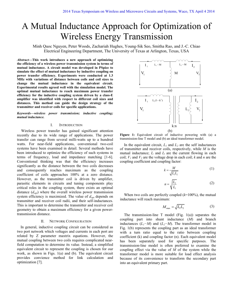
In general, inductive coupling circuit can be considered as two port network which voltages and currents in each port are related by Z parameter maxtrix equations. However, the mutual coupling between two coils requires complicated nearfield computation to determine its value. Instead, a simplified equivalent circuit to represent the coupling is chosen for our work, as shown in Figs. 1(a) and (b). The equivalent circuit provides convience method for link calculation and optimization [7]. k:n
(b)
Figure 1: Equivalent circuit of inductive powering with (a) a transmission-line T model and (b) an ideal transformer model.
In the equivalent circuit, L
1
and L
2
are the self inductances of transmitter and receiver coils, respectively, while M is the mutual inductance; I
1
and I
2
are the current flowing in each coil; V
1
and V
2
are the voltage drop in each coil; k and n are the coupling coefficient and coupling factor: k
M
L L
2
(1) n
L
2
L
1
(2)
When two coils are perfectly coupled ( k =100%), the mutual inductance will reach maximum:
M max
L L
1 2
(3)
The transmission-line T model (Fig. 1(a)) separates the coupling part into shunt inductance ( M ) and branch inductances ( L
1
−M ) and ( L
2
−M ). The transformer model in
Fig. 1(b) represents the coupling part as an ideal transformer with a turn ratio equal to the ratio between coupling coefficient (k) and coupling factor (n). Each equivalent model has been separately used for specific purposes. The transmission-line model is often preferred to examine the coupling effect via the value of M of the system while the transformer model is more suitable for load effect analysis because of its convenience to transform the secondary part into an equivalent primary part.
R
1 d
Figure 2 : Maxwell coaxial filament loops.
R
2
The mutual inductance can also be measured by the short and open circuit method [9]. The measured mutual inductances of each coil-pair are used in the calculation to simplify the simulation.
From Fig. 1(a), the driving impedance seen from the transmitter coil can be represented by:
Z
1
V
1 (8)
I
1
In general, mutual inductance between any pair of loops which have arbitrary shape and relative position can be calculated by:
M
12
12
I
1
s
2
Bds
2
(4)
I
1
If the receiver coil is open ( I
2
=0):
Z
1 open
I
1
(
1
M )
jwM
I
1
jwL
1
(9)
For coaxial filament loops, as shown in Fig. 2, with the assumption of current is uniformly distributed on the coil length (when the physical length of coil is much smaller than the wavelength), mutual inductance can be expressed in the closed form by [8]:
M
0
R R
2
(
2 g
2 g
E
(5) where µ
0
is the free-space permeability; R
1
and R
2
are the radii of coils; d is the distance between two coils; K and E are the complete elliptic integrals of the first kind and second kind to the modulus g , respectively, and
If the receiver coil is short, the shunt inductance ( M ) and branch inductance ( L
2
−M ) form a parallel circuit:
Z
1 short
(
1
M )
(
2
M )
jwM
(
2
M )
jwM
Z
1 open
jwM 2
(10)
L
2
From Eqs. 9 and 10, M can be rewritten as:
M
1
Z
1 short
Z
1 open
L L
2
(11) g
( R
1
4 R R
2
R
2
) 2
d 2
(6)
For multiple winding loops, M can be calculated by Eq. 5:
M
'
N N M
1 2
(7) where N
1 and N
2
are the winding numbers of coil; M is the mutual inductance between two single loops.
Equation 11 introduces a simple method to measure the mutual inductance between two coils at any position. Mutual inductance between a fixed transmitter coil and three receiver coils with different coil radius as a function of distance is shown in Fig. 3. M decays rapidly with increasing coil spacing and also with decreasing coil radius, as expected.
In the wireless power transfer system, we used an n-channel high-efficiency low power switching MOSFET (IRF510) class-E amplifier to amplify the 1.3-MHz signal from a function generator (Fig. 4).
The MOSFET was connected to a power supply through an inductor L
E
. The Drain and Source pins of the transistor were connected to a capacitor C
E
. L
E
and C
E
formed an LC shunt circuit to ground. The Gate was trigger by a 1.3-MHz 50% duty-cycle square-waveform signal. Output voltage was measured at the load to calculate the output power while the input voltage and current from the DC supply were measured to obtain the input power. System efficiency ( n% ) was calculated as the ratio between output and input powers, which included both wireless power transfer efficiency ( n e
%) and the class-E amplifier efficiency ( n
PA
% ): n
%
n
PA
%
n e
% (12)
Figure 3 : Mutual inductance as a function of distance between a transmitter coil with a 21 cm coil radius, and three 21-cm, 17-cm and
13-cm radius receiver coils.
III.
S IMULATION A NALYSIS
A model was developed in PSpice to examine the effect of
M on the system efficiency (Fig. 4). Transmission line
I dc
V dc L
E
C
1
R
1
L
1
-M L
2
-M R
2
1.3MHz
C
E
I
1
M
I
M
I
2
C
2
R load
Class-E
Amp
Transmitter circuit Inductive coupling Receiver circuit
Figure 4 : Circuit model in PSpice. equivalent circuit shown in Fig. 1(a) was used to represent the inductive coupling. C
1
and C
2
are the matching capacitors in the transmitter and receiver tuning to resonance. R
1
, R
2
and
R load
are the equivalent resistances of transmitter coil, receiver coil and load, respectively.
The transmitter coil inductance L
1
was fixed at 100 µH. The receiver coil L
2
was designed with 3 different values of inductances (100µH, 200µH and 400µH) representing three different receiver coil radii (13 cm, 17cm and 21 cm). The mutual inductance M was varied from 5µH to 60µH. A fixed value of mutual inductance resulted in different spacings for different coil radii. For example, with a mutual inductance set at 20µH, the spacings for 21-cm, 17-cm and 13-cm radius receiver coils to the transmitter coil became 30 cm, 20 cm and
10 cm, respectively. Parameters used in simulations are given in Table 1.
The system power transfer efficiency as a function of mutual inductance with different receiver coils is shown in Fig.
5. Conventional understanding is that the efficiency should have increased as the mutual inductance increases and reaches maximum when two coils are perfectly coupled at zero spacing. However, the simulations indicated that there exists an optimal value of mutual inductance M opt when the efficiency reaches maximum. For the receiver coil self-inductances of
L
2
=100µH, 200µH and 400µH, the M opt is close to 20µH.
Table I
S IMULATION P ARAMETERS
Coil
Parameters
Transmitter Receiver
Inductance (µH)
Coil radius (cm)
100
21
100
200
400
13
17
21
Load resistance (Ω)
C
E
(pF)
L
E
(µH)
Frequency (MHz)
500
1000
100
1.3
V dc
(V) 6
Figure 5 : System power transfer efficiency as a function of mutual inductance for 3 different receiver coil self inductances of L
2
=100µH,
200µH and 400µH.
The efficiency does not seem to significantly depend on the receiver self-inductance or the optimal mutual inductance.
IV.
E XPERIMENT V ERIFICATION
Experiments were conducted with the configuration in Fig.
4. A class-E amplifier was used to amplify the voltage swing at
1.3 MHz across the transmitter coil. The receiver coil was connected to a resistive load of 500 Ω. The load was chosen for the specific application for stomach tissue stimulation [10]. The transmitter coil was fixed with a 21-cm radius with a measured self-inductance of 109.1µH. The receiver coils were designed with 3 different radii of 13, 17 and 21 cm. The inductances of the receiver coils were measured as 105.6µH, 195.2µH, and
401.8µH, respectively.
For three sets of receiver coils, the spacing between each transmitter and receiver coil pair was varied from 5 cm to 60 cm in steps of 5 cm. The input voltage and current, as well as the output voltage were measured to calculate the overall power transfer system efficiency. Fig. 6 shows the results.
When the distance between TX and RX was relatively large, mutual inductance was very small as shown in Fig. 3. The current I
1
from transmitter circuit mostly circulated through the shunt inductance M while delivering only a small portion to receiver circuit, therefore the output power and system efficiency was very low. When the distance became closer, mutual inductance started to increase, providing more current flowing to the receiver circuit and improving system efficiency. However, M was still small and the mismatch between C
1
, C
2
and L
1
M , L
2
M was within acceptable tolerance. System was within resonance condition with such small variation of M . When the distance continued to be even closer, at a certain point, M became significant. In such cases,
C
1
, C
2 were no longer matched with L
1
M , L
2
M . The system was off from the resonance condition and the driving impedance of class-E amplifier circuit became mismatched with the input impedance of the equivalent inductive coupling circuit seen from the class-E amplifier. The impedance mismatch detuned the class-E amplifier efficiency and significantly reduced the overall system efficiency. The
Figure 6 : Comparison of experiment results (labels) and simulation ones (solid lines) for power transfer system efficiency as a function of distance for three different receiver coil radii of 13, 17, and 21 cm. maximum system efficiencies obtained for receiver coils of 13 cm, 17 cm and 21 cm radius were 46%, 48% and 44% at spacings of 10 cm, 20 cm and 30 cm, respectively. At the peak efficiencies, the mutual inductances were measured as 21.9µH,
22.3µH and 21.4µH. The mutual inductances to reach a maximum efficiency, M opt
, in these cases are basically the same indicating the validity of the simulation model. The spacing distance however to reach a maximum efficiency is dependent of receive coil cross section, as it increases with a larger coil. This is expected since a larger cross section of coil couples more fields into the wire, thus it takes a larger spacing to reach the required mutual inductance of M opt
.
In a new design, the equivalent circuit method can be used first to determine the optimal mutual inductance required to reach the maximum power transfer efficiency. Then the coils can be designed for a user-desired spacing distance. Since the inductances are determined, the parameters left to decide are the coil turn numbers if the coil radii are constrained by physical dimensions. The system efficiency then can be tuned to maximum, despite the conventional thinking that the maximum efficiency is usually at the zero spacing.
V.
C ONCLUSION
The effect of mutual inductance on wireless power transfer system efficiency was examined by both simulation and experiments. The overall system efficiencies including the efficiencies of the driving class-E power amplifier for different coil radius and spacing were examined. A maximum system efficiency for power transfer can be achieved at an optimal mutual inductance. This indicates that an optimal spacing distance can be achieved to obtain the maximum system efficiency given any pair of transmitter and receiver coils. This method can help to optimize the design of coil parameters and arrangement to accomplish high wireless power transfer efficiency. In this work, the system efficiency was optimized considering roles of self and mutual inductances which affected class-E amplifier operation and the coupling distance.
The physical impact of field distribution in space was not considered as it was simplified as mutual inductance.
However, when the coils misalign the field coupling will vary and the coupling coefficient, or the mutual inductance, will change. The future work will focus on investigation of effects from the coil misalignment utilizing the similar proposed equivalent circuit method.
A CKNOWLEDGMENTS
We sincerely thank Texas Instruments, Texas Health
Resources, Intel, and Vietnam International Education
Development for their support.
[1]
[2]
[3]
R EFERENCES
S. Kong,
et al .,
“Analytical expressions for maximum transferred power in wireless power transfer systems,” IEEE
International Symposium on Electromagnetic Compatibility , pp.
379-383, Rome, Italy, Aug. 2011.
H. Park, et al ., “A design of high efficiency class-E power amplifier for wireless power transfer system,” IEEE MTT-S
International Microwave Workshop Series on Intelligent Radio for Future Personal Terminals, pp. 1-2, Daejeon, Korea, Aug.
2011.
W. Hsu, et al ., “A Wireless Power Pickup Based on Directional
Tuning Control of Magnetic Amplifier,” IEEE Transactions on
Industrial Electronics , Vol. 56, No. 7, pp. 2771-2781, Jul. 2009.
[4]
[5]
[6]
R. Harrison, “Designing Efficient Inductive Power Links for
Implantable Devices,” IEEE International Symposium on
Circuits and Systems , pp. 2080-2083, New Orleans, USA, May.
2007.
A. RamRakhyani, “Design and Optimization of Resonance-
Based Efficient Wireless Power Delivery Systems for
Biomedical Implants,” IEEE Transactions on Biomedical
Circuits and Systems , Vol. 5, No. 1, pp. 48-63, Feb. 2011.
R. Jegadeesan and Y. X. Guo, “Evaluation and Optimization of
High Frequency Wireless Power links,” IEEE International
Symposium on Antennas and Propagations , pp. 400-403,
Spokane, USA, Jul. 2011.
[7] K. Schuylenbergh, “Inductive Powering Basic Theory and
Application to Biomedical Systems,” Springer, 2009.
[8]
[9]
[10]
S. Babic, “The Mutual Inductance of Two Thin Coaxial Disk
Coils in Air,” IEEE Transactions on Magnetics , Vol. 40, No. 2, pp. 822–825, 2004.
S. Hackl , et al
., “A Novel Method for Determining the Mutual
Inductance for 13.56 MHz RFID systems,”
International
Symposium Com. Sys., Net. and DSP.
, pp. 297–300, July 2008.
S. Deb, et. al ., “An Endoscopic Wireless Gastrostimulator (with video),”
Gastrointestinal Endoscopy , Vol. 75, No. 2, pp 411–
415, 2012.


