Document
advertisement
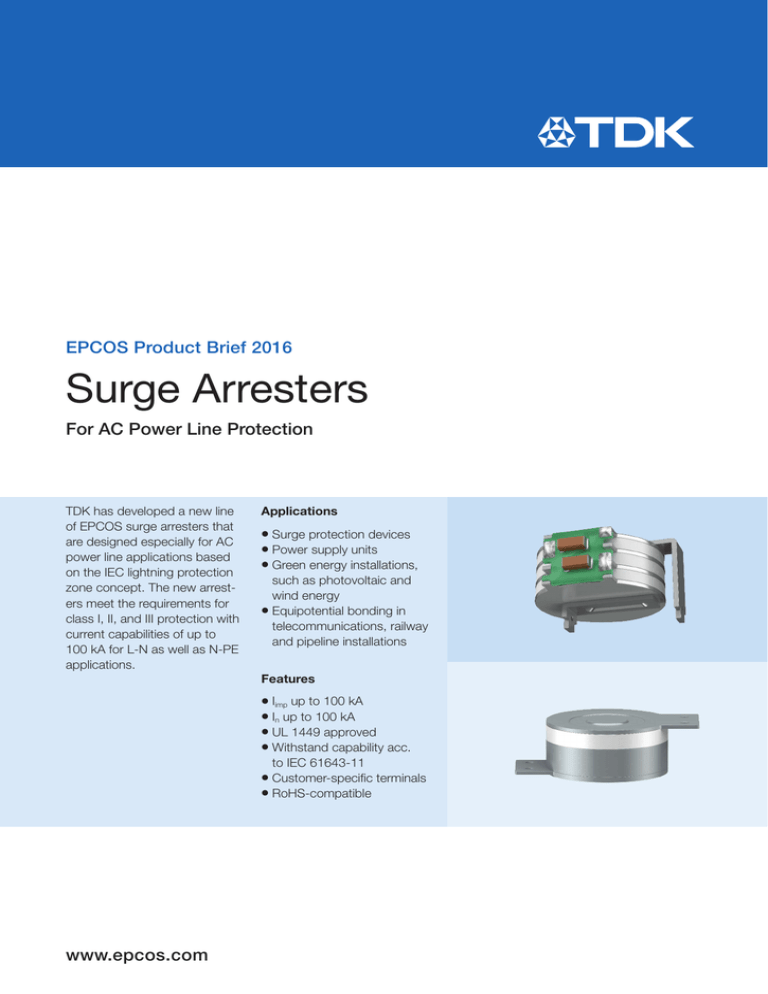
EPCOS Product Brief 2016 Surge Arresters For AC Power Line Protection TDK has developed a new line of EPCOS surge arresters that are designed especially for AC power line applications based on the IEC lightning protection zone concept. The new arresters meet the requirements for class I, II, and III protection with current capabilities of up to 100 kA for L-N as well as N-PE applications. Applications zz Surge protection devices supply units zz Green energy installations, such as photovoltaic and wind energy zz Equipotential bonding in telecommunications, railway and pipeline installations zz Power Features zz Iimp up to 100 kA up to 100 kA zz UL 1449 approved zz Withstand capability acc. to IEC 61643-11 zz Customer-specific terminals zz RoHS-compatible zz In www.epcos.com Surge Arresters for L-N and N-PE Application Class I & II surge protection LN30B-… H38M-… D38T28M-… D3E14M-… D3B-… Type Ordering code LN30B-A1800AC-3C B88069X3643B201 H38M-A800XP1 D38T28MB88069X3993B201 A1000P1-2 upon request D3E14M-A800XP1 D3B-A700XP upon request B88069X2513B401 Approx. size w/o terminals 31 × 37 × 12 Ø 30 × 28 Ø 30 × 26 Ø 30 × 14 Ø 30 × 4 Class I & II I I I I & II Application for L-N N-PE N-PE N-PE N-PE Nom. DC spark-over voltage VsdcN 1800 800 1000 800 700 V > 600 > 600 > 800 > 600 > 550 V Up < 2500 < 1500 < 2200 < 1500 < 1500 V Max. continuous operating voltage @ 50/60 Hz Uc 275 255 440 264 264 V Nominal discharge current 8/20 μs In 25 100 100 100 30 kA Impulse current 10/350 μs limp 25 100 100 100 25 kA Follow current @ 50/60 Hz If 6000 100 100 100 100 A Max. continuous operating voltage @ 50/60 Hz Uc 275 – – – 264 V Nominal discharge current 8/20 μs In 25 – – – 30 kA Max. discharge current 8/20 μs lmax 40 – – – 40 kA Follow current @ 50/60 Hz If 6000 – – – 100 A AC discharge current (TOV at 1200 V, connected N-PE) 1 operation 50 Hz, 0.2 s – 300 300 300 300 A Max. temporary over voltage (max. 5 s) for L-N 440 – – – – V Insulation resistance > 10 >1 >1 >1 >1 GΩ DC spark-over voltage Front of wave spark-over voltage @ 1.2/50 µs, 6 kV Class I Class II Arresters are designed in accordance with IEC 61643-11. 2 For further information please contact our sales office. © EPCOS AG 2016 Surge Arresters for N-PE Application Class II & III surge protection A81-… M51-… V13-… V84-… Type Ordering code A81-A700XP2 B88069X1623 M51-A800XP B88069X4781 V13-A800XP2 B88069X9821 V84-A1200XP2-2 upon request Approx. size w/o terminals Ø8×6 Ø5×5 Ø 12 × 17 Ø 12 × 16 Class II & III II & III II II N-PE N-PE N-PE N-PE 800 800 1200 V > 550 > 600 > 600 > 900 V Up < 1500 < 1500 < 1500 < 2500 V Max. continuous operating voltage @ 50/60 Hz Uc 255 255 255 440 V Nominal discharge current 8/20 μs In 10 3 20 20 kA Maximum discharge current 8/20 µs lmax 20 3 40 40 kA Follow current @ 50/60 Hz If 100 5 100 100 A AC discharge current (TOV at 1200 V, connected N-PE) 1 operation 50 Hz, 0.2 s – – 300 300 A Insulation resistance >1 >1 >1 >1 GΩ Application for Nom. DC spark-over voltage VsdcN 700 DC spark-over voltage Front of wave spark-over voltage @ 1.2/50 µs, 6 kV Class II Class III Max. continuous operating voltage @ 50/60 Hz Uc 255 255 – – V Limiting voltage at combination wave generator, 1.2/50 μs, 6 kV; 8/20 μs, 3 kA Up < 1500 < 1500 – – V Arresters are designed in accordance with IEC 61643-11. © EPCOS AG 2016 For further information please contact our sales office. 3 Surge Arresters for N-PE Applications with Varistors in Series Class I, II & III surge protection V87A-… A80-… L18A-… V13M-… Type Ordering code V87A-A300XSPD B88069X2453B251 A80-A900XPD B88069X2523C103 L18A-A3000XPD B88069X9471B122 V13M-H40XPD B88069X3313B251 Approx. size w/o terminals Ø 12 × 13 Ø8×6 Ø 30 × 13 Ø 12 × 17 Class I, II & III (with varistor in series) II (with varistor in series) I & II (with varistor in series) II (with varistor in series) Application for N-PE N-PE N-PE N-PE Nom. DC spark-over voltage VsdcN 300 900 3000 4000 V 225 … 375 > 700 2700 … 3900 > 3200 V Up < 900 < 1700 < 4500 < 5500 V Max. continuous operating voltage @ 50/60 Hz Uc 110 – 1000 – V Nominal discharge current 8/20 μs In 20 – 50 – kA Impulse current 10/350 μs limp 12.5 – 35 – kA Max. continuous operating voltage @ 50/60 Hz Uc 110 255 1000 440 V Nominal discharge current 8/20 μs In 20 10 50 15 kA Maximum discharge current 8/20 µs lmax 40 20 100 30 kA >1 >1 >1 >1 GΩ DC spark-over voltage Front of wave spark-over voltage @ 1.2/50 µs, 6 kV Class I Class II Insulation resistance Class III Max. continuous operating voltage @ 50/60 Hz Uc 110 – – – V Limiting voltage at combination wave generator, 1.2/50 μs, 6 kV; 8/20 μs, 3 kA Up < 650 – – – V Arresters are designed in accordance with IEC 61643-11. © EPCOS AG 2016 For further information please contact our sales office. 4 Applications of Surge Arresters Lightning protection zone concept Building entrance Direct lightning Installation/ Distribution induced current Equipment protection Class I Class II Class III L3 L2 L1 FI LN N V1*-XN L1* H3* L1* A8*-XP M5*-XP PE Fuse Arrester Inductor/ Transformer Varistor RAB0339-F-E L-N/N-PE arresters are applicable in TN, TT and IT systems. Above figure shows the TN-C-S system. Class I Surge arrester protects against direct lightning strike. Direct lightning strike is defined as current impulse Iimp with waveform 10/350 µs. Withstand capability acc. to IEC 61643-11 standard (up to 100 kA). Class II Surge arrester protects against induced surge current. Induced surge current is defined as current impulse In and Imax with waveform of shorter duration than Iimp, 8/20 µs. Withstand capability acc. to IEC 61643-11 standard. Class III Surge arrester protects against induced voltage spikes and induced surge currents with 8/20 µs waveform and lower surge currents (few kA). Withstand capability acc. to IEC 61643-11 standard. 5 For further information please contact our sales office. © EPCOS AG 2016 Symbols and Terms Description of EPCOS specific terms P (M51-A800XP) Surge arrester for class I & II, class II & III or class I, II & III applications. Surge withstand capability for Iimp, In and Imax impulses. P1 (H38M-A800XP1) Surge arrester for class I application. Surge withstand capability for Iimp and In impulses. P2 (V13-A800XP2) Surge arrester for class II or class II & III applications. Surge withstand capability for In and Imax impulses. PD (A80-A900XPD) Surge arrester as device with other downstream current limiting components, e.g. varistor in series. Definitions of key parameters L-N Surge current will be diverted by arrester between L-phase and N-neutral. L-PE Surge current will be diverted by arrester between L-phase and PE-ground. N-PE Surge current will be diverted by arrester between N-neutral and PE-ground. Ucov V Maximum continuous operating voltage Voltage that can be applied continuously to the surge arrester. Up V Voltage protection level Maximum voltage at the surge arrester terminals with an impulse with defined voltage steepness. Impulse waveform of 1.2/50 µs at 6 kV with a steepness of 5 kV/µs acc. to IEC 61643-11. DC spark-over V voltage Spark-over voltage Voltage at the surge arrester terminals due to an voltage impulse with low rate of rise, around 100 V/s. Breakdown time ns Reaction time of surge arrester Time to switch from high ohmic state to protection mode. In protection mode the arrester is in a low ohmic conducting state, equipment will be protected. In kA Nominal discharge current Current through the surge arrester with a waveform 8/20 µs for class I and II. Iimp kA Impulse discharge current Current through the surge arrester with a waveform 10/350 µs for class I. If A Imax kA Maximum discharge current Peak value of a current through the surge arrester that has an 8/20 waveform. TOV Follow current Current supplied by the electrical power system and flowing through the surge arrester after an In – discharge current impulse. Temporary overvoltage Alternating current through surge arrester caused by faults in the power voltage system. For example: 300 A at 1200 V for a duration of 200 ms. Structure of ordering codes: The ordering code for one and the same product can be represented differently in data sheets, data books, other publications and the website of EPCOS, or in order-related documents such as shipping notes, order confirmations and product labels. The varying representations of the ordering codes are due to different processes employed and do not affect the specifications of the respective products. Detailed information can be found on the Internet under www.epcos.com/orderingcodes. Important information: Some parts of this publication contain statements about the suitability of our products for certain areas of application. These statements are based on our knowledge of typical requirements that are often placed on our products. We expressly point out that these statements cannot be regarded as binding statements about the suitability of our products for a particular customer application. It is incumbent on the customer to check and decide whether a product is suitable for use in a particular application. This publication is only a brief product survey which may be changed from time to time. Our products are described in detail in our data sheets. The Important notes (www.epcos.com/ImportantNotes) and the product-specific Cautions and warnings must be observed. All relevant information is available through our sales offices. © EPCOS AG · A TDK Group Company Edition 05/2016 · Ordering No. EPC:48014-7600 · Printed in Germany · PB 05161.

