LAB ACTIVITY 2- MODULE 1 - HALF WAVE - AnalogElectronics-CM
advertisement

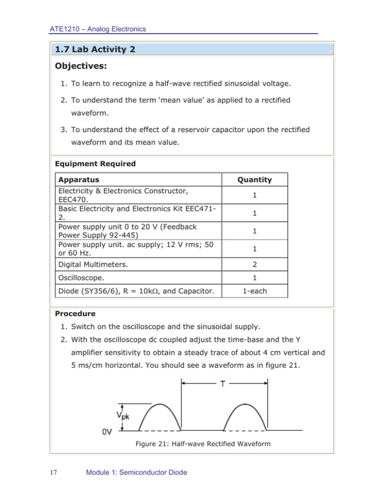
ATE1210 – Analog Electronics 1.7 Lab Activity 2 Objectives: 1. To learn to recognize a half-wave rectified sinusoidal voltage. 2. To understand the term ‘mean value’ as applied to a rectified waveform. 3. To understand the effect of a reservoir capacitor upon the rectified waveform and its mean value. Equipment Required Apparatus Quantity Electricity & Electronics Constructor, EEC470. Basic Electricity and Electronics Kit EEC4712. Power supply unit 0 to 20 V (Feedback Power Supply 92-445) Power supply unit. ac supply; 12 V rms; 50 or 60 Hz. 1 1 1 1 Digital Multimeters. 2 Oscilloscope. 1 Diode (SY356/6), R = 10k:, and Capacitor. 1-each Procedure 1. Switch on the oscilloscope and the sinusoidal supply. 2. With the oscilloscope dc coupled adjust the time-base and the Y amplifier sensitivity to obtain a steady trace of about 4 cm vertical and 5 ms/cm horizontal. You should see a waveform as in figure 21. Figure 21: Half-wave Rectified Waveform 17 Module 1: Semiconductor Diode ATE1210 – Analog Electronics 3. As shown in the patching diagram of figure 22, construct the circuit of figure 23. Figure 22: Constructor-EEC470 Figure 23: Half-wave Rectification 4. Measure and record the time T and the ge Vpk 5. Sketch the waveform and label it to show the periods when the diode is conducting and those when it is not. 6. Time T depends upon the frequency of your power supply. For a 50Hz supply it should be 20 ms and for 60 Hz it should be 17ms. 7. Confirm this: Vpk should be very nearly equal to the peak voltage of the alternating supply. 18 Module 1: Semiconductor Diode ATE1210 – Analog Electronics Questions 1) Why will Vpk not be exactly equal to this voltage? ………………………………………………………………………………………………………… ………………………………………………………………………………………………………… 2) How much will it differ? Hint: The mean value of a half-sinusoid can be shown by geometry to be: ………………………………………………………………………………………………………… ………………………………………………………………………………………………………… ………………………………………………………………………………………………………… 3) Note the mean voltage indicated by the voltmeter, and compare it with the calculated value. ……………………………………………………………..……………… 4) The mean voltage you obtain is positive relative to zero. How could you obtain a negative voltage? (Confirm your answer by experiment). ………………………………………………………………………………………………………… Conclusion: x A simple diode circuit can convert a/an ………………………… voltage to a/an ……………………………voltage. x The mean value of the rectified voltage can be increased by using a ……………………………………………………… across the load. x A half-wave rectified voltage gives appreciable ripple which however, can be reduced by ………………………………………………………. 19 Module 1: Semiconductor Diode


