Binary to Gray Code Converter & Decoder Experiment
advertisement
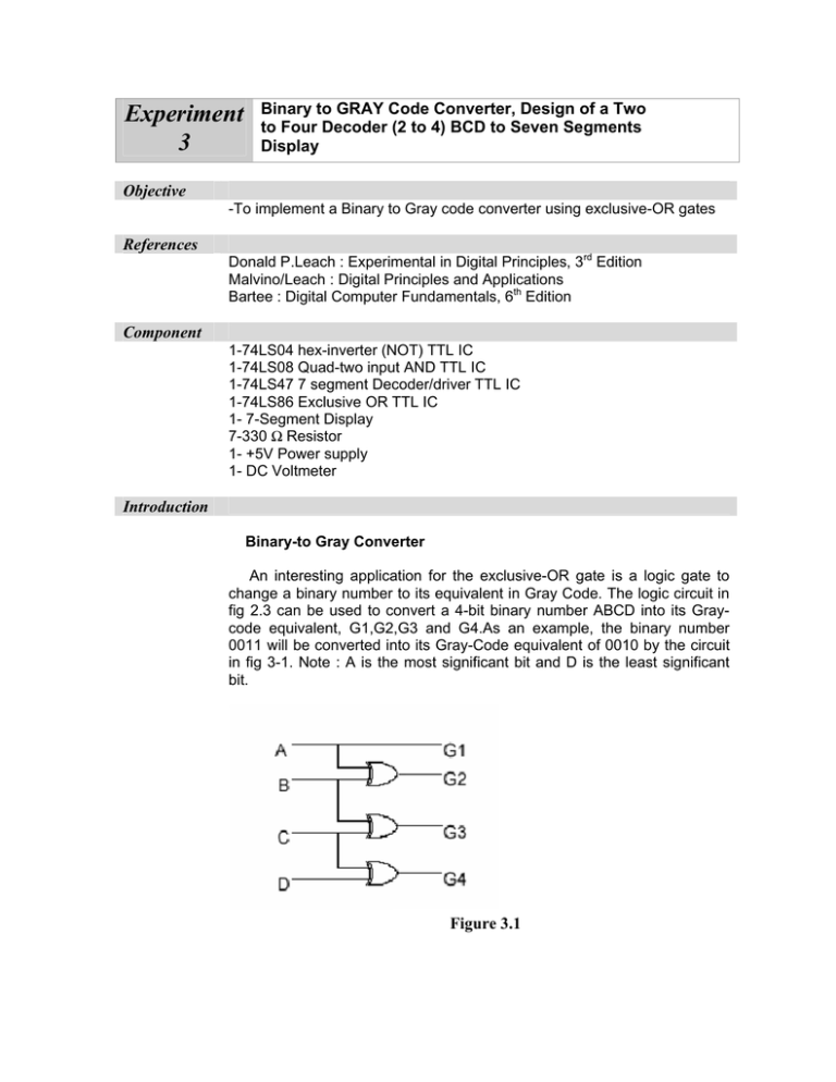
Experiment 3 Binary to GRAY Code Converter, Design of a Two to Four Decoder (2 to 4) BCD to Seven Segments Display Objective -To implement a Binary to Gray code converter using exclusive-OR gates References Donald P.Leach : Experimental in Digital Principles, 3rd Edition Malvino/Leach : Digital Principles and Applications Bartee : Digital Computer Fundamentals, 6th Edition Component 1-74LS04 hex-inverter (NOT) TTL IC 1-74LS08 Quad-two input AND TTL IC 1-74LS47 7 segment Decoder/driver TTL IC 1-74LS86 Exclusive OR TTL IC 1- 7-Segment Display 7-330 Ω Resistor 1- +5V Power supply 1- DC Voltmeter Introduction Binary-to Gray Converter An interesting application for the exclusive-OR gate is a logic gate to change a binary number to its equivalent in Gray Code. The logic circuit in fig 2.3 can be used to convert a 4-bit binary number ABCD into its Graycode equivalent, G1,G2,G3 and G4.As an example, the binary number 0011 will be converted into its Gray-Code equivalent of 0010 by the circuit in fig 3-1. Note : A is the most significant bit and D is the least significant bit. Figure 3.1 7-Segment Display A 7-segment Display is a chip were seven LED’s are constructed and arranged in the pattern shown in fig-3-2. Figure 3.2 There are 2 type of 7-Segment Display : 1) Common Anode (C.A): Where all the anodes of the seven LED’s are connected together. 2) Common Cathode (C.C): Where all the cathodes of the seven LED’s are connected together. 7- Segment Decoder Driver The 7-segment decoder driver is a device which can be used to drive a 7-segment LED. There are 2 types of decoder driver corresponding to the two different 7-segment configurations(C.A;C.C). Procedure 1) Using the 74LS86 to construct the binary-to-Gray converter shown in Fig 3-1. Verify the proper operation of the circuit by applying at least 3 different inputs signals and record the resulting outputs in the table 1 below. Table 1 2) Using the same concept design a 5 bit binary-to Gray converter. Verify the Gray code of the following inputs : Note : no need to construct circuit experimentally. a) 11001 b) 01011 3) Design a circuit that will implement the truth table shown in table 2. Explain what the circuit does, where (A,B are inputs) and (Y1, Y2, Y3, Y4 are outputs) Note : no need to construct circuit experimentally. Table 2 4) Set up the circuit shown in fig 3-3. Verify BCD to 7- segment code conversion by completing the truth table III. Before that find out the pin configuration of the 7-segment display (i.e diodes a,b,c,d,e,f and g) Questions 1. Design the circuit that will convert form Gray to Binary. 2. How do you convert the output states of the decoder circuit in procedure 2 to active LOW. 3. Verify what is the different between common anode and common cathode circuit for the 7-segment display 4. Why was a 330 ohm resistor included in the wiring?
