Hall Sensor Testing
advertisement

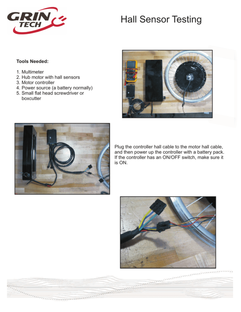
Hall Sensor Testing Tools Needed: 1. Multimeter 2. Hub motor with hall sensors 3. Motor controller 4. Power source (a battery normally) 5. Small flat head screwdriver or boxcutter Plug the controller hall cable to the motor hall cable, and then power up the controller with a battery pack. If the controller has an ON/OFF switch, make sure it is ON. Hall Sensor Testing Make sure your multimeter has the black probe in the COM slot and the red probe in the V? Hz slot. Switch the multimeter to DC voltage mode and turn the dial to the “20V” setting The multimeter is now ready for use Hall Sensor Testing Now probe with the multimeter (if you have an eZee motor controller or motor please see appendix) between the red (V+) and black (ground) hall wires - you might need to push the probes in with a little bit of force to get contact. You should see somewhere from 4V to 5V. With this series of tests it doesn’t matter which way round the probes go - the only difference is that you’ll see a negative voltage if you reverse the them. If you have issues getting the probes to fit in the back of the housing then you can try putting a small pin or nail in first and then use the probe on that. Next probe between the ground (black) and yellow, ground and blue, and ground and green wires. Yellow Blue Green As you turn the wheel slowly backwards you should see the voltage continually switch between 0V and 5V (if you turn a geared motor like an eZee forwards the halls won’t change because the motor freewheels in that direction). When you stop turning the wheel the voltage for each hall sensor will be sat at either 0V or 5V. If one of the hall’s voltage doesn’t switch then you either have an issue with the wiring for that hall or an issue with the actual hall itself. Also, if you spin the wheel too fast you will see a steady 2.5V which is just the average between 0V and 5V. Hall Sensor Testing Appendix for eZee motor controllers and motors The eZee motor controller hall connector has glue and heatshrink around it that make it tricky to probe the individual hall wires. One solution is to put a small pin or nail through the glue until you make contact with the connector pin and then use the multimeter probes on that. Another solution is to use a small flathead screwdriver or boxcutter and make small cuts in the insulation surrounding the wires so that you can probe with a multimeter. It is best to stagger these cuts in order to reduce the risk of shorting two wires together. Once the tests have been done it’s advisable to cover these cuts with tape or glue.


