UV/IRS Flame Detector
Product Data Sheet
FGD-PDS-UV-IRS-Flame-Detector
July 2015
UV/IRS Flame Detector
Ultraviolet and Infrared Optical Sensors
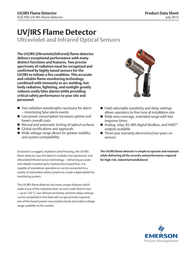
The UV/IRS (Ultraviolet/Infrared) flame detector
delivers exceptional performance with many
distinct functions and features. Two precise
spectrums of radiation must be recognized and
confirmed by highly tuned sensors for the UV/IRS to initiate a fire condition. This accurate
and reliable flame monitoring technology
combined with immunity to arc welding, hot
body radiation, lightning, and sunlight greatly
reduces costly false alarms while providing
critical safety performance to your site and
personnel.
Two radiation wavelengths necessary for alarm – minimizing false alarm events
Low power consumption increases uptime and
lowers overall costs
Manual and automatic testing of optical surfaces
Global certifications and approvals
Wide voltage range allows for greater stability
and system compatibility
Field-selectable sensitivity and delay settings
allows operators to fine tune at installation site
Wide area coverage, extended range with fast
response times
Analog, relay, RS-485 digital Modbus, and HART®
outputs available
Three year warranty electronics/two years on
sensors
Enclosed in a rugged, explosion-proof housing, the UV/IRS
flame detector uses the latest in modular microprocessor and
Ultraviolet/Infrared sensor technology — delivering accurate
and reliable monitoring for hydrocarbon based fires. It is
capable of standalone operation or can be connected to a
variety of networked safety systems to create a dependable fire
monitoring system.
The UV/IRS flame detector is simple to operate and maintain
while delivering all the security and performance required
for high-risk, industrial installations!
The UV/IRS flame detector has many unique features which
make it one of the industries best: an extra wide field of view
— up to 120 °C; user defined sensitivity and time delay settings
can be completed in the field with no special tools required;
one of the lowest power consumption levels and widest voltage
range available on the market.
July 2015
UV/IRS Flame Detector
Specifications
Table 1 - UV/IRS Flame Detector
Analog
Relay
HART®
Operating Voltage Range
10 to 32 VDC
Power Consumption
at 24 VDC
*with Heater
Nom 45 mA/1.1 W
Max 115 mA/2.76 W
*Nom 90 mA/2.16 W
*Max 165 mA/3.96 W
Nom 45 mA/1.1 W
Max 115 mA/2.76 W
*Nom 90 mA/2.16 W
*Max 165 mA/3.96 W
Nom 71 mA/1.7 W
Max 173 mA/3.36 W
*Nom 106 mA/2.22 W
*Max 223 mA/5.36 W
Power Consumption
at 32 VDC
*with Heater
Nom 35 mA/1.12 W
Max 105 mA/3.36 W
*Nom 70 mA/2.24 W
*Max 145 mA/4.64 W
Nom 35 mA/1.12 W
Max 105 mA/3.36 W
*Nom 70 mA/2.24 W
*Max 145 mA/4.64 W
Nom 57 mA/1.72W
Max 158 mA/5.06 W
*Nom 92 mA/2.84 W
*Max 198 mA/6.34 W
Temperature Range
Certified -40 °C to +75 °C (-40 °F to +167 °F)
Field of View
120° horizontal/95° vertical
Spectral Range
UV Radiation 185 to 260 nm (1850 to 2600 angstroms) | IR Radiation in the 4.4 µm range
Time Delay
DIP switch selectable to 0, 3, 5, 7 s
Sensitivity Settings
DIP switch selectable to 8, 16, 24 or 32 counts per s
Response Time
< 6 seconds [depending on fuel source, fire size and distance]
Enclosure Material
Red powder coated with clear anodizing, 6061 aluminum (optional 316 stainless steel), factory sealed housing
Humidity Range
0 to 95 % RH, non-condensing
Weight (with Swivel)
2.1 kg/4.5 lb (Stainless Steel option 3.4 kg/7.5 lb) - does not include junction boxes
Outputs
0 to 20 mA (±0.2 mA) - Into a
maximum loop impedance of
800 Ohms or 150 Ohms at
11.0 VDC
Non-isolated loop supply
Form C contacts rated 1 A at
30 VDC, 0.5 A at 125 VAC
Selectable energized/de-energized,
latching/non-latching Fire relay Fault
relay factory set as energized/nonlatching, cannot be modified
HART®
Certifications/Approvals
CSA - Class I, Division 1, Groups B, C and D - Temperature code T5 - CANADA: Class I, Zone 1, Ex d IIB + H2 T5
ANSI/UL - Class I, Division 1, Groups B, C and D - Temperature code T5
- UNITED STATES: Class I, Zone 1, AEx d IIB + H2 T5
ATEX/IECEx - II 2 G Ex d II B+H2 T5 Gb
INMETRO - Ex d II B+H2 T5 Gb
FM approved per approval standard 3260
NEMA Type 4X • IP66 - Enclosure ratings
Audit finding: 10-December 2014
Warranty
Three years electronics/Two years sensors
Table 2 - Ordering Information
UV/IRS
4–20 mA analog output
(JB-MPS-A/S included)
UV/IRS-AR
4–20 mA analog output with a fire and
fault alarm relay
(JB-MPR-A/S included)
UV/IRS-AH
4–20 mA analog output and HART®
(JB-MPHF-A/S included)
UV/IRS-AHR
4–20 mA analog output and fire and fault
alarm relays and HART®
(JB-MPHFR-A/S included)
2
Additional Approvals: –X (ATEX/IECEx)
Enlcosure Material: Stainless Steel (–SS) [Aluminum is Standard]
Additional Features: –H (Heated Optics)
Ordering Matrix Example:
UV/IRS-AHR-X-SS-H
(Detector - Output - Additional Approval - Enclosure Material - Optional Features)
www.EmersonProcess.com/Safety
July 2015
UV/IRS Flame Detector
Separation Boxes & Accessories
Table 2 - Summary of Distances
Table 3 - Immunity False Alarm Stimuli
Fuel
Fire Size
Typical Response
Stimuli
Immunity Range
n-heptane
1 in x 1 in
< 11 s @ 140 ft
Direct/indirect sunlight
Total
Gasoline
1 in x 1 in
< 6 s @ 120 ft (< 3 s @ 50 ft)
1500 W heater
10 ft
Methane
32 in plume
< 6 s @ 100 ft
Halogen, incandescent light
3 ft
Florescent light
10 ft
Arc welding
30 ft
Figure 1 - Example Field of View - Methane
32'' plume - indicated in feet - consult factory for other gases
30°
15°
0°
100
15°
80
45°
45°
60
60°
¾'' NPT
30°
5.89''
2.96''
0.25''
60°
40
Detector
Head
20
0.50''
35°
30°
4.12''
15°
0°
15°
60°
45°
30°
2.60''
Vertical Field of View
with Detector at 45°
from Horizontal
VI Reflector
Yellow Dot
Align with center
of Reflector
UV Emitter
Red LED
UV Sensor
Yellow LED
Green LED
IR Emitter
IR Sensor
Table 4 - Termination Boxes
Class I, Division 1, Groups BCD - Class I, Zone 1 – Enclosure rated NEMA 4X, IP67
JB-MPS-A/S
Termination box - analog output - switch (for remote MVI testing) and test jacks - aluminum or stainless steel
Table 5 - Accessories
LAT-120
Laser alignment tool assembly - used to define area of coverage for all flame detectors
AIR-SHIELD
Air shield assembly (aluminum). supplied clean instrument air keeps lens clear in areas with heavy airbourne particulate
HPT-001
HART communicator port - intrinsically safe connection mounts to connected JB-MPHF and JB-MPHFR
FH-SHROUD
Field of view restrictor anodized (red) for “S” series fire detectors (aluminum)
UN-MK-41
One inch pipe mounting kit - stainless steel
UN-MK-42
Two inch pipe mounting kit - stainless steel
UN-MK-43
Three inch pipe mounting kit - stainless steel
SSK-4
Sunshade kit/rain guard for “S” series flame, stainless steel - mounts directly to flame detector
SSK-1
Sunshade kit for “S” series flame, stainless steel - mounts directly to flame detector
TL-MP-KIT
Universal test lamp kit - certified rechargeable hand-held unit - produces accurate fire simulation (UV and IR sources)
TL-MP-KIT-X
Universal test lamp kit [ATEX] - certified rechargeable hand-held unit - produces accurate fire simulation (UV and IR sources)
www.EmersonProcess.com/Safety
3
UV/IRS Flame Detector
Product Data Sheet
FGD-PDS-UV-IRS-Flame-Detector
July 2015
www.RosemountAnalytical.com
www.analyticexpert.com
www.twitter.com/RAIhome
www.youtube.com/user/RosemountAnalytical
www.facebook.com/EmersonRosemountAnalytical
Scan the QR code with
your smartphone to go
to our website.
©2015 Emerson Process Management. All rights reserved.
HEADQUARTERS
Emerson Process Management
Flame & Gas Detection
2721 Hopewell Place NE
Calgary, Alberta, Canada T1Y 7J7
T +1 (403) 219 0688
T +1 866 347 3427
F +1 (403) 219 0694
safety.csc@emerson.com
www.emersonprocess.com/safety
The Emerson logo is a trademark and service mark of Emerson Electric Co. Rosemount Analytical
is a mark of Emerson Process Management family of companies. All other marks are the property
of their respective owners.
The contents of this publication are presented for information purposes only, and while
effort has been made to ensure their accuracy, they are not to be construed as warranties or
guarantees, express or implied, regarding the products or services described herein or their use
or applicability. All sales are governed by our terms and conditions, which are available on request
We reserve the right to modify or improve the designs or specifications of our products at any
time without notice.


