Lesson 12
advertisement

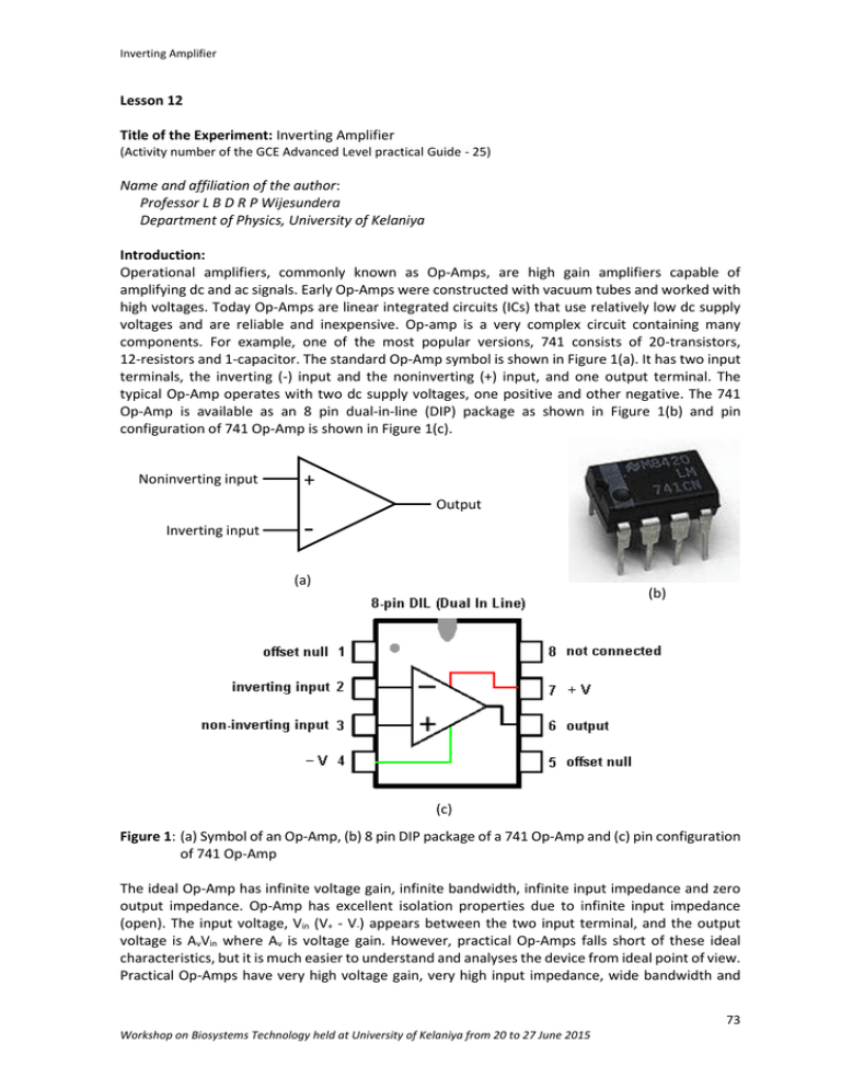
Inverting Amplifier Lesson 12 Title of the Experiment: Inverting Amplifier (Activity number of the GCE Advanced Level practical Guide - 25) Name and affiliation of the author: Professor L B D R P Wijesundera Department of Physics, University of Kelaniya Introduction: Operational amplifiers, commonly known as Op-Amps, are high gain amplifiers capable of amplifying dc and ac signals. Early Op-Amps were constructed with vacuum tubes and worked with high voltages. Today Op-Amps are linear integrated circuits (ICs) that use relatively low dc supply voltages and are reliable and inexpensive. Op-amp is a very complex circuit containing many components. For example, one of the most popular versions, 741 consists of 20-transistors, 12-resistors and 1-capacitor. The standard Op-Amp symbol is shown in Figure 1(a). It has two input terminals, the inverting (-) input and the noninverting (+) input, and one output terminal. The typical Op-Amp operates with two dc supply voltages, one positive and other negative. The 741 Op-Amp is available as an 8 pin dual-in-line (DIP) package as shown in Figure 1(b) and pin configuration of 741 Op-Amp is shown in Figure 1(c). Noninverting input + Output Inverting input (a) (b) (c) Figure 1: (a) Symbol of an Op-Amp, (b) 8 pin DIP package of a 741 Op-Amp and (c) pin configuration of 741 Op-Amp The ideal Op-Amp has infinite voltage gain, infinite bandwidth, infinite input impedance and zero output impedance. Op-Amp has excellent isolation properties due to infinite input impedance (open). The input voltage, Vin (V+ - V-) appears between the two input terminal, and the output voltage is AvVin where Av is voltage gain. However, practical Op-Amps falls short of these ideal characteristics, but it is much easier to understand and analyses the device from ideal point of view. Practical Op-Amps have very high voltage gain, very high input impedance, wide bandwidth and 73 Workshop on Biosystems Technology held at University of Kelaniya from 20 to 27 June 2015 Inverting Amplifier very low output impedance. Op-Amps have both voltage and current limitations. Output voltage is usually limited to slightly less than the two supply voltages. Output current is also limited by internal restrictions such as power dissipation and component rating. Due to the very high gain, Op-Amp cannot be used as it is to amplify signals. Op-Amps are generally accompanied by feedback circuits that define and control the properties of the Op-Amp circuit. OpAmp’s output connects to one of its inputs, either directly or indirectly. This situation is called feedback; when feedback is employed we say that the op-amp is operating in the closed-loop mode when no feedback is employed, we say that the op-amp is operating in the open-loop mode. Inverting amplifier is an example for the closed-loop mode operation and voltage comparator is an example for open-loop mode operation. Power supply for 741 Op-Amp Vc dc voltage source is needed to operate 741 Op-Amps and it can be achieved using laboratory dual rail dc power supply or two batteries which are connected as shown in Figure 2. - - + - Vc + Ground + Vc Figure 2: Vc supply setup using two batteries Theory: This experiment investigates the Op‐Amp inverting amplifier circuit in closed loop operation. The gain is determined by the ratio of resistors R1 and R2 and by measuring the input and output voltages, Vin and Vout respectively. Consider the circuit shown in Figure 3. +9 V SW1 Rf -9 V 10k +9 V 1k Potentiometer Rin Vin 2 7 - 10k 6 + 3 Vo 4 Rm = Rin//Rf -9 V Figure 3: Inverting amplifier with gain = 1 Voltage gain of the circuit = Av = - 𝑉𝑜𝑢𝑡 𝑉𝑖𝑛 =- 𝑅𝑓 𝑅𝑖𝑛 𝑉𝑜𝑢𝑡 = −𝐴𝑣 𝑉𝑖𝑛 y = m x Gain of the amplifier can be obtained from the gradient of the graph of Vout Vs Vin and R1/R2. 74 Workshop on Biosystems Technology held at University of Kelaniya from 20 to 27 June 2015 Inverting Amplifier Learning outcomes: In this experiment you will study the characteristics of an inverting amplifier. At the end of this experiment you should be able to select the proper values of external components for designing an inverting dc amplifier having desired gain. Materials/Equipment: 741 op-amp, 9 V dual rail power supply, breadboard, two voltmeter, two 1 k, 10 k resistors, one 4.7 k resistor, 1 k potentiometer, connecting wires Methodology/Procedure: 1. Connect the circuit as shown in Figure3. Show the circuit to your demonstrator before turning on the power to the circuit. 2. Connect switch SW1 to +9 V. 3. Set Vin = 100 mV by adjusting the potentiometer. Measure the output voltage. 4. Repeat step 3 for the input voltages given in the sample data sheet. 5. Connect switch SW1 to -9 V. 6. Set Vin = -100 mV by adjusting the potentiometer. Measure the output voltage. 7. Repeat step 6 for the input voltages given in the sample data sheet. 8. Tabulate the output voltages in the sample data sheet. 9. Replace the Rin by 1 k resistor and repeat the step 2 to 8. 10. Complete the columns given in the sample data sheet. 11. Plot the Vo versus Vin curves for the inverting amplifiers. 12. Calculate the gains of the amplifier using gradients of the graphs. Readings/Observations: Vin (mV) Vo (mV) Rin = 10 k Rf/Rin Vo/Vin Vo (V) Rin = 1 k Rf/Rin Vo/Vin 100 200 300 400 -100 -200 -300 -400 75 Workshop on Biosystems Technology held at University of Kelaniya from 20 to 27 June 2015 Inverting Amplifier Graphs: Calculations: When Rin = 10 k, Gain = Gradient = When Rin = 1 k, Gain = Gradient = Discussions: Conclusions: References: Botkar, K. L. (1996). Integrated Circuits, Khanna Publishers. Clayton, G. and Winder, S. (2003). Operational Amplifiers, 5th Edition, Newnes Publications. Floyd, T. L. (2013). Electronic Devices (Conventional Current Version), 9th Edition, PrenticeHall International. Horowitz, P. and Hill, W. (1997). The Art of Electronics, 2nd Edition, Cambridge University Press. 76 Workshop on Biosystems Technology held at University of Kelaniya from 20 to 27 June 2015


