Mounting Instructions for Packaged FETs and MMICs
advertisement
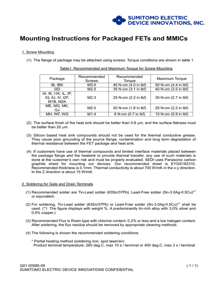
Mounting Instructions for Packaged FETs and MMICs 1. Screw Mounting (1) The flange of package may be attached using screws. Torque conditions are shown in table 1. Table1. Recommended and Maximum Torque for Screw Mounting Package IB, IBK I2D IA, IK, I1K, IL, IP, IQ, IU, IV, I2F, M1B, M2A ME, MG, MK, GJ MH, WF, WG Recommended Screws M3.0 M2.5 Recommended Torque 45 N-cm (4.0 in lbf) 35 N-cm (3.1 in lbf) 50 N-cm (4.4 in lbf) 40 N-cm (3.5 in lbf) M2.3 25 N-cm (2.2 in lbf) 30 N-cm (2.7 in lbf) M2.0 20 N-cm (1.8 in lbf) 25 N-cm (2.2 in lbf) M1.4 8 N-cm (0.7 in lbf) 10 N-cm (0.9 in lbf) Maximum Torque (2) The surface finish of the heat sink should be better than 0.8 m, and the surface flatness must be better than 20 m. (3) Silicon based heat sink compounds should not be used for the thermal conductive grease. They cause poor grounding of the source flange, contamination and long term degradation of thermal resistance between the FET package and heat sink. (4) If customers have use of thermal compounds and limited interface materials placed between the package flange and the heatsink to provide thermal transfer, any use of such materials is done at the customer’s own risk and must be properly evaluated. SEDI uses Panasonic carbon graphite sheet for mounting our devices. Our recommended sheet is EYGS182310. Recommended thickness is 0.1mm. Thermal conductivity is about 700 W/mK in the x-y direction. In the Z direction is about 15 W/mK. 2. Soldering for Gate and Drain Terminals (1) Recommended solder are Tin-Lead solder (63Sn/37Pb), Lead-Free solder (Sn-3.0Ag-0.5Cu)*1 or equivalent. (2) For soldering, Tin-Lead solder (63Sn/37Pb) or Lead-Free solder (Sn-3.0Ag-0.5Cu)*1 shall be used. (*1: The figure displays with weight %. A predominantly tin-rich alloy with 3.0% silver and 0.5% copper.) (3) Recommended Flux is Rosin type with chlorine content: 0.2% or less and a low halogen content. After soldering, the flux residue should be removed by appropriate cleaning methods. (4) The following is shown the recommended soldering conditions. * Partial heating method (soldering iron, spot laser/air) Product terminal temperature: 260 deg.C, max 10 s / terminal or 400 deg.C, max 3 s / terminal Q01-00585-09 SUMITOMO ELECTRIC DEVICE INNOVATIONS CONFIDENTIAL ( 1 / 1)
