Applications of Ampere`s Law
advertisement

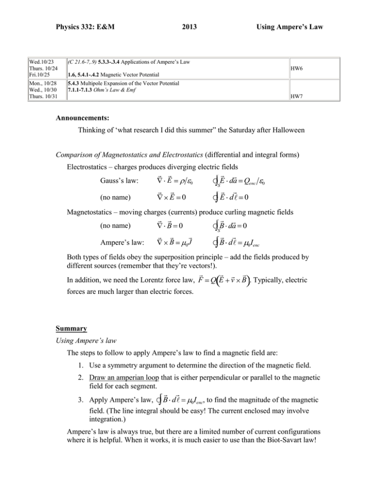
Physics 332: E&M 2013 Wed.10/23 Thurs. 10/24 Fri.10/25 (C 21.6-7,.9) 5.3.3-.3.4 Applications of Ampere’s Law Mon., 10/28 Wed., 10/30 Thurs. 10/31 5.4.3 Multipole Expansion of the Vector Potential 7.1.1-7.1.3 Ohm’s Law & Emf Using Ampere’s Law HW6 1.6, 5.4.1-.4.2 Magnetic Vector Potential HW7 Announcements: Thinking of ‘what research I did this summer” the Saturday after Halloween Comparison of Magnetostatics and Electrostatics (differential and integral forms) Electrostatics – charges produces diverging electric fields Gauss’s law: (no name) E 0 E 0 E da Qenc S E d 0 0 Magnetostatics – moving charges (currents) produce curling magnetic fields (no name) Ampere’s law: B 0 B B da 0 S 0 J B d I 0 enc Both types of fields obey the superposition principle – add the fields produced by different sources (remember that they’re vectors!). In addition, we need the Lorentz force law, F Q E v B . Typically, electric forces are much larger than electric forces. Summary Using Ampere’s law The steps to follow to apply Ampere’s law to find a magnetic field are: 1. Use a symmetry argument to determine the direction of the magnetic field. 2. Draw an amperian loop that is either perpendicular or parallel to the magnetic field for each segment. 3. Apply Ampere’s law, B d 0 Ienc, to find the magnitude of the magnetic field. (The line integral should be easy! The current enclosed may involve integration.) Ampere’s law is always true, but there are a limited number of current configurations where it is helpful. When it works, it is much easier to use than the Biot-Savart law! What Ampere’s Law Does not say (applies for whole loop, not segments) Note that Ampere’s law says it is the complete loop integral that depends exclusively on the piercing current – it does not say that the field or even B dl over a given segment must depend only on the piercing current. If you imagine three parallel wires and draw an Amperian loop around just one of them, certainly the field at every point on the loop is influenced by all three currents; however, Ampere’s law does say that, when you integrate over the whole loop – the contributions of external currents cancel out of the sum. We noted something similar for Gauss’s Law last time – you get the simple result only when you sum flux through the whole surface. Also, in this form, it only speaks for continuous currents – that is, it cannot handle a single moving point charge. Using Ampere’s Law to find the Magnetic Field: Like Gauss’s Law, Ampere’s Law is of particular use when the field geometries are simple. For some distributions of charge, Ampere’s law to determine the magnitude of the magnetic field. 4. Field Geometry. Use a symmetry argument to determine the direction of the magnetic field 5. Amperian Loop. Draw a Amperean loop that is either perpendicular or parallel to the magnetic field 6. Math. Apply Ampere’s law to find the magnitude of the magnetic field A. Thick Current-Carrying Wire A long, thick wire of radius R carries a current I. Field Geometry. Use a symmetry argument to determine the direction of the magnetic field near the center of the wire’s length. o We have cylindrical symmetry in the current flow, so we must have cylindrical symmetry in the magnetic field. That necessitates that, at any point a distance r from the center of the wire, the field must have the same strength and the same direction (in terms of r and ), so that if the wire is rotated, the field, just like the current, looks unchanged. Generally, this says the field looks like: n̂ r 2 No Radial Component by Gauss’s Law o Note: as illustrated, symmetry arguments alone don’t force the field to be tangential to the surface. That comes from Gauss’s Law for Magnetism: B nˆ dA 0 o Imagine for a moment that we enwrap the wire in a Gaussian shell, our Amperian ring is just a cross-section of that. Applying symmetry, we still have that B is constant and of constant orientation relative to the area everywhere on the surface, so Bsin dA Bsin L r 0 . The only way to make this equal zero as we know it must is for sin =0, or = 90°. No z-component by Biot-Savart Law d J rˆ 0 o Br so B’s got to be perpendicular to the current 4 r2 density, J, which itself is in the z direction. Amperian Loop. What shape of Amperean loop can you draw so that the magnetic field is tangent or perpendicular to each segment? r Math. Use Ampere’s law to find the magnitude of the magnetic field at a radial distance r from the center of the wire for: r R Now, applying Ampere’s Law gives B d 0 I inside path B2 r B I 0 inside path I 0 inside path 2 r Exactly what we have for an infinitesimally thin wire. In fact, notice that the only assumption that we made about the current density was that it was cylindrically symmetric: that covers a line current (no width), a hollow shell of current, and everything in between – say, a current that drops of across the radius of the wire. As long as it’s radially symmetric, the field looks the same. r R if we assume uniform current density, I/A, then… 3 Hollow wire. Look at the case of a hollow shell of current: R r The math woks out just the same: B d 0 I inside path B2 r B I 0 inside path for r>R I 0 inside path 2 r What about inside this hollow tube of current? The symmetry and Gaussian arguments are the same, but Iinside is 0, so inside B = 0. Coaxial Cable Now, what about a Coaxial cable? That’s got a thin wire in the middle, carrying current one way, and a hollow tube encircling it and carrying equal and opposite current. R The field inside the tube is purely due to the inner wire, B I , r<R 2 r 0 wire While the field outside is due to both of the wire and tube of current, B I 2 r 0 wire I , r>R, 2 r 0 tube but if they have equal and opposite currents, then the two terms cancel so B = 0 , r>R. 4 That, in fact, is one of the appeals of coaxial wires. The book goes through a number of the Common Cases 1. Straight lines / Cylindrical symmetry (prototype: Ex. 5.7) current in direction of an axis (call it z) i. Note: looking at the Biot-Savart Law, with J×r, we know that field can’t be in this direction the current density only depends on the distance s from the axis, J J s zˆ Since the divergence of B =0, there can be no net radial B; since B is angularly symmetric on account of the source itself being angularly symmetric (if you rotate it you can’t tell the difference), this rules out there being some local radial-in component being balanced by a local radial-out component somewhere else – there can be no radial component. the magnetic field is circumferential in the direction given by the RHR and Bs ˆ can only depend on the distance from the axis, B 2. Planar symmetry (prototype: Ex. 5.8) suppose that the current flows in the x direction the current density is symmetric about a plane (call it the xy plane), J J z xˆ the magnetic field must be in the y direction (use RHR) and can only B z yˆ depend on the distance from the plane, B 3. Long (infinite) Solenoids (prototype: Ex. 5.9) the current is circumferential around a cylinder, usual given in terms of number of turns per length (n) the current along the axis is very small if n is large, so the circumferential component of the magnetic field is approximately zero (Fig. 5.36) the magnetic field must be parallel to the axis (call it z) , B can be argued that the field outside is zero (Fig. 5.37) B s zˆ , and it Can argue then that, if you make two different amperian loops that differ only by how far out the side of the solenoid they extend, if there were field outside the solenoid, the external, parallel leg’s contribution to B d 0 Ienc should vary with separation from the solenoid (since it 5 really should be 0 infinitely far away). But if that’s the case, then, since the same I is enclosed, it would mean that the contribution from the leg inside the solenoid is varying for no good physical reason. Since that can’t be, the field outside must be everywhere 0. 4. Toroids (prototype: Ex. 5.10) – different approach taken from Wangsness N turns of wire wrapped around a toroid (donut shape) and carrying current I In the diagram, the solid lines are “out of the page and the dashed ones are “into the page”. Also, a small number of N is shown, but it is large. Consider the four paths shown: C1, C2, C3, and C4 (side view also shown) Top View of Toroidal Coil Cross Section of Toroidal Coil 6 These figures adapted from ones in Electromagnetic Fields by Roald Wangsness. 7 Paths C1, C2, and C3 can be used to determine the component of the magnetic field as a function of the distance s from the center (O) of the “donut” (using cylindrical coordinates with +z upward). For all of three of these paths, the line integral is B d B 2 s. The current enclosed by the paths is zero for paths C1 and also for C3 because the same current passes downward (positive) and upward (negative). The current enclosed for path C2 is NI. Applying Ampere’s law, B d 0 Ienc, gives (cross sectional shape of toroid doesn’t matter) 0 outside, inside. 0I 2 s B The current enclosed by path C4 is I, so the z and s components of the magnetic field are smaller by a factor of about 1/N. Typically, they negligible. Examples/Exercises: Coaxial Cables: Suppose a long, thin wire carries a current I in the +z direction and a thin cylindrical shell of radius a carries the same current in the opposite direction. Find the magnetic field everywhere. The magnetic field can only be circumferential, so use a circle of radius s as the amperian loop in the ˆ direction (as shown below). I a I s The line integral is enclosed is B d B 2 s , regardless of the size of the loop. The current I s a, 0 s a. Ienc For a loop outside the cable, the current enclosed is zero because the current on the two parts is in opposite directions (one is positive and the other is negative). Applying Ampere’s law, B d 0 Ienc, gives B 0 I 2 s ˆ 0 s a, s a. 8 Thick Solenoid: Suppose a solenoid is made of several wraps of thin wire. The inner radius of the solenoid is a, the outer radius is b, the number of wires per area is , and the current is I. Find the magnetic field everywhere. Let the solenoid be centered on the z axis and suppose the current flows in the ˆ direction. By the RHR, the magnetic field is in the +z direction inside the solenoid. Using the same kinds of paths as in Example 5.9, it can be argued that the magnetic field outside is zero (the magnetic field must be the same on the vertical sides and the right one can be moved far away where it must go to zero). z a b s L I Consider a loop like the one drawn above with the left side at a distance s < b from the axis. The line integral is B d Bz L . The current enclosed is (number of wires times current of one): Ienc B d Applying Ampere’s law, B Lb aI s a, Lb sI a s b. I , gives 0 enc 0 0 b a I zˆ s a, b s I zˆ a s b. 9 Problem 5.15: Two long coaxial solenoids each carry current I, but in opposite directions (see figure below). The inner solenoid of radius a has n1 turns per length and the other one of radius b has n 2 turns per length. Find the magnetic field everywhere. Find the magnetic field of each solenoid and add them to get the total magnetic field (superposition principle). Don’t forget to take the direction into account because the fields are vectors! The magnetic field for the inner solenoid points to the left (RHR), so n I zˆ s a, 0 s a. 0 1 B1 The magnetic field for the outer solenoid points to the right (RHR), so n I zˆ s b, 0 s b. 0 2 B2 Adding these fields gives 0 B B1 B2 I n 2 n1 zˆ s a, ˆ a s b, 0n2I z 0 s b. Problem 5.16 (a) A large parallel-plate capacitor with uniform surface charge on the upper plate and – on the lower one is moving with a constant speed v (see the figure below). (a) Find the magnetic field everywhere. z y Qu ic kTime ™ and a TIFF (Unco mpres se d) d eco mpres so r are n eed ed to se e thi s pi cture. x Use the coordinate system shown above. Find the magnetic field of each solenoid and add them to get the total magnetic field (superposition principle). Don’t forget to take the direction into account because the fields are vectors! For both plates, the size of the surface current density is K K v xˆ , so the magnetic field is v . For the upper plate, 10 Bupper For the lower plate, K Blower 0 2 0 2 v yˆ below the upper plate, v yˆ above the upper plate. v xˆ , so the magnetic field is (by RHR) 0 2 0 2 v yˆ below the lower plate, v yˆ above the lower plate. The total magnetic field is B Bupper Blower 0 0 outside of the plates, v yˆ between the plates. Preview Next time, we’ll discuss the magnetic vector potential. Just skim Example 5.11. Pay more attention to Example 5.12. "How does the symmetry argument for the uniform infinite plane go again?"Casey McGrath "Why is it that we only have three Gaussian configurations (plane, cylinder, sphere) when finding the E field, but four Amperian configurations when finding the B field?"Spencer "Could we talk a little bit about how Griffiths is able to get the field inside and outside a solenoid from Ampere's law? The example (5.9) is pretty clear up until he finds that it is zero outside and has a value inside the solenoid."Ben Kid "Can we do an example of a Biot-Savart Law calculation where the perpendicular distance isnt the same across dl? (Sorry, I know its a bit of review)"Freeman, Nappleton "Im somewhat confused about the formation of the magnetic field of a surface and the argument made in ex:5.8."Antwain "At the end of the reading, Griffiths talks about neutral current-carrying wires to maintain balance between electric and magnetic fields. I've never thought of it in this way, nor am I recognizing it's obvious. Do you think you could elaborate?"Rachael Hach "What is an example in which Ampere's law is not useful?" Davies "The book states that no one has ever found a magnetic monopole in nature. This implies that they are in fact theoretically possible. Why can we not rule out their existence?" Casey P, AHoN swag 4 liphe "Can we go over some examples of finding the field of various configurations, esp. the solenoid argument, which I had trouble understanding." Sam "Can we do an example problem that uses amperes law that's not so simple like the examples in the book. Like where I enclosed is not so obvious?" Jessica 11


