Small-Signal Analysis Steps
advertisement
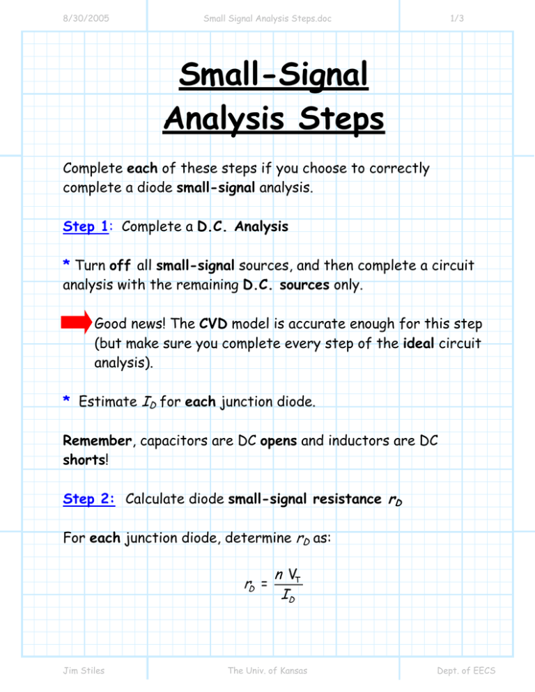
8/30/2005 Small Signal Analysis Steps.doc 1/3 Small-Signal Analysis Steps Complete each of these steps if you choose to correctly complete a diode small-signal analysis. Step 1: Complete a D.C. Analysis * Turn off all small-signal sources, and then complete a circuit analysis with the remaining D.C. sources only. Good news! The CVD model is accurate enough for this step (but make sure you complete every step of the ideal circuit analysis). * Estimate ID for each junction diode. Remember, capacitors are DC opens and inductors are DC shorts! Step 2: Calculate diode small-signal resistance rD For each junction diode, determine rD as: rD = Jim Stiles n VT ID The Univ. of Kansas Dept. of EECS 8/30/2005 Small Signal Analysis Steps.doc 2/3 Step 3: Replace junction diode with a small-signal PWL model The ideal diode in the PWL model will be in the same bias state as the ideal diode in the CVD model in step 1. In other words, if you determined in step 1 that an ideal diode is forward biased, then rest assured the same ideal diode is forward biased in this step! Step 4: Determine the small-signal circuit. * Turn off all D.C. sources. Remember: A zero voltage source is a short. A zero current source is an open. More good news! Since source VDO is a DC source, then we set it to zero--there is no need to calculate VD0 ! * Approximate all DC blocking capacitors as AC short circuits in your small-signal circuit (i.e., remove all blocking capacitors in the schematic, and replace them with short circuits). * Approximate all AC choke inductors as AC open circuits in our small-signal circuit (i.e., remove all choke inductors in the circuit schematic, and replace them with short circuits). Jim Stiles The Univ. of Kansas Dept. of EECS 8/30/2005 Small Signal Analysis Steps.doc 3/3 Step 5: Analyze the small-signal circuit. Analyze the circuit with small-signal sources only, to find all small-signal voltages and currents. It will likely be helpful to simplify and redraw the resulting small-signal circuit. Since a bunch of the original circuit devices (e.g., DC sources, inductors, capacitors) may have been replaced with shorts and opens, the resulting small-signal circuit can often be greatly simplified. Hint: Your small-signal currents and voltages cannot and must not have a DC component! If they do, it means that you have left “on” one or more DC sources! For example, if id is the smallsignal current through the diode, then the small signal voltage vd across the diode is: vd = id rD Thus, answers such as vd = id rD + 0.7 or vd = id rD +VD 0 are not correct! Jim Stiles The Univ. of Kansas Dept. of EECS

