APPLICATION NOTE
No. 831: Temperature Coefficients of Dielectric Resonators
Introduction
Our previous Tech-Brief1 detailed some of the advantages of the
substitution of conventional microwave resonators by dielectric
resonators (D.R.s). Better circuit performance with respect to
temperature variations was mentioned among others. The design
of D.R. temperature compensated circuits involves an understanding of the relationship between the different temperature
coefficients. The purpose of this Tech-Brief is to present an introduction to the definitions, properties and measurements of the
temperature coefficients of cylindrical D.R.s.
Definitions
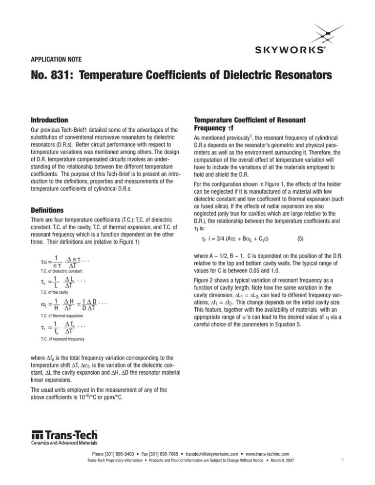
There are four temperature coefficients (T.C.): T.C. of dielectric
constant, T.C. of the cavity, T.C. of thermal expansion, and T.C. of
resonant frequency which is a function dependent on the other
three. Their definitions are (relative to Figure 1)
τ∈=
T.C. of dielectric constant
∆L ...
∆T
T.C. of the cavity
αL = 1 ∆ H = 1 ∆ D . . .
H ∆T
D ∆T
T.C. of thermal expansion
τf = 1
fo
As mentioned previously1, the resonant frequency of cylindrical
D.R.s depends on the resonator’s geometric and physical parameters as well as the environment surrounding it. Therefore, the
computation of the overall effect of temperature variation will
have to include the variations of all the materials employed to
hold and shield the D.R.
For the configuration shown in Figure 1, the effects of the holder
can be neglected if it is manufactured of a material with low
dielectric constant and low coefficient to thermal expansion (such
as fused silica). If the effects of radial expansion are also
neglected (only true for cavities which are large relative to the
D.R.), the relationship between the temperature coefficients and
τf is:
τf i = 3/4 (Aτε + BαL + Cτc)
(5)
where A ~ 1/2, B ~ 1. C is dependent on the position of the D.R.
relative to the top and bottom cavity walls. The typical range of
values for C is between 0.05 and 1.0.
1 ∆ ∈τ . . .
∈τ ∆T
τc = 1
L
Temperature Coefficient of Resonant
Frequency τf
∆ fo . . .
∆T
Figure 2 shows a typical variation of resonant frequency as a
function of cavity length. Note how the same variation in the
cavity dimension, ∆L1 = ∆L2, can lead to different frequency variations, ∆f1 = ∆f2. This change depends on the initial cavity size.
This feature, together with the availability of materials with an
appropriate range of τε‘s can lead to the desired value of τf via a
careful choice of the parameters in Equation 5.
T.C. of resonant frequency
where ∆fo is the total frequency variation corresponding to the
temperature shift ∆T, ∆εT, is the variation of the dielectric constant, ∆L the cavity expansion and ∆H, ∆D the resonator material
linear expansions.
The usual units employed in the measurement of any of the
above coefficients is 10-6/°C or ppm/°C.
Phone [301] 695-9400 • Fax [301] 695-7065 • transtech@skyworksinc.com • www.trans-techinc.com
Trans-Tech Proprietary Information • Products and Product Information are Subject to Change Without Notice. • March 9, 2007
1
APPLICATION NOTE • NO. 831 TEMPERATURE COEFFICIENTS OF DIELECTRIC RESONATORS
Measurement
The measurement of τf can be easily performed in any test setup
capable of precise resonant frequency measurements. A resolution of at least seven digits read out in the GHz range is required.
Figure 3 is an example using the impedance method to track the
change in resonant frequency of the D.R. with temperature. The
microwave signal is coupled to the D.R. located in a cylindrical
test cavity via a H-field probe.
Values of τf given in Trans-Tech specifications bulletins are measured on test samples of 0.500” dia. by 0.200” thickness. The
sample is centered in a cavity of 1.500” dia. by 1.050” height.
The room temperature resonant frequency of the cavity plus D.R.
is about 4.2 GHz. A practical example of the strong effect of the
top and bottom cavity walls on the temperature coefficient of resonant frequency is given for Trans-Tech dielectric resonator type
D-8512. In a parallel plate cavity with the metallic walls in contact with the D.R., a τf of +9 ppm/°C is obtained. When
measured in the quality control standard cylindrical cavity
described above, the value of τf is reduced to +4.0 ppm/°C. It is
worthwhile noting that manufacturers measure the Q of dielectric
resonators at different frequencies. A general phenomenological
equation can be utilized to estimate the Q at any frequency.
fo • Q = 40,000
(6)
where fo is the resonant frequency. For example, a material with
a Q of 10,000 at 4 GHz will have a Q of 5,000 at 8 GHz.
In summary, care must be exercised in selecting a D.R. material
of correct value to obtain overall device temperature stability.
Figure 1
Figure 2
Figure 3
Trans-Tech compliments its product line of Dielectric Resonators
by offering materials with various temperature coefficients of
Resonant Frequency, abbreviated τf. The purpose of offering a
variety of τf is to allow the designer control of frequency drift vs.
temperature.
The τf is expressed in ppm/°C. In this context, the meaning is 1 Hz
change for each MHz of operating frequency. For example, if an
oscillator running at 10,750 MHz (10.750 GHz) decreases in frequency by a total of 1.5 MHz over a -20 °C to + 70°C temperature
range, the temperature coefficient of the oscillator circuit, Tc, is
6
tc = -1.5 X 10 Hz
10750 MHz
1
X (70- -20)
= -1.55 ppm/°C
This oscillator could be compensated for near-zero temperature
drift by changing the tf of the dielectric resonator by + 2ppm/°C.
TTI recommends that first design iterations begin with zero coefficient, τf = 0.
References:
(1) Tech-Brief No. 821 - An Introduction to Dielectric Resonators.
Phone [301] 695-9400 • Fax [301] 695-7065 • transtech@skyworksinc.com • www.trans-techinc.com
2
March 9, 2007 • Trans-Tech Proprietary Information • Products and Product Information are Subject to Change Without Notice.
APPLICATION NOTE • NO. 831 TEMPERATURE COEFFICIENTS OF DIELECTRIC RESONATORS
Copyright © 2006, 2007, Trans-Tech Inc., Inc. All Rights Reserved.
Information in this document is provided in connection with Trans-Tech, Inc. ("Trans-Tech"), a wholly-owned subsidiary of Skyworks Solutions, Inc. These materials, including the information
contained herein, are provided by Trans-Tech as a service to its customers and may be used for informational purposes only by the customer. Trans-Tech assumes no responsibility for errors
or omissions in these materials or the information contained herein. Trans-Tech may change its documentation, products, services, specifications or product descriptions at any time, without
notice. Trans-Tech makes no commitment to update the materials or information and shall have no responsibility whatsoever for conflicts, incompatibilities, or other difficulties arising from
any future changes.
No license, whether express, implied, by estoppel or otherwise, is granted to any intellectual property rights by this document. Trans-Tech assumes no liability for any materials, products or
information provided hereunder, including the sale, distribution, reproduction or use of Trans-Tech products, information or materials, except as may be provided in Trans-Tech Terms and
Conditions of Sale.
THE MATERIALS, PRODUCTS AND INFORMATION ARE PROVIDED "AS IS" WITHOUT WARRANTY OF ANY KIND, WHETHER EXPRESS, IMPLIED, STATUTORY, OR OTHERWISE, INCLUDING FITNESS FOR A
PARTICULAR PURPOSE OR USE, MERCHANTABILITY, PERFORMANCE, QUALITY OR NON-INFRINGEMENT OF ANY INTELLECTUAL PROPERTY RIGHT; ALL SUCH WARRANTIES ARE HEREBY EXPRESSLY
DISCLAIMED. TRANS-TECH DOES NOT WARRANT THE ACCURACY OR COMPLETENESS OF THE INFORMATION, TEXT, GRAPHICS OR OTHER ITEMS CONTAINED WITHIN THESE MATERIALS. TRANS-TECH
SHALL NOT BE LIABLE FOR ANY DAMAGES, INCLUDING BUT NOT LIMITED TO ANY SPECIAL, INDIRECT, INCIDENTAL, STATUTORY, OR CONSEQUENTIAL DAMAGES, INCLUDING WITHOUT LIMITATION,
LOST REVENUES OR LOST PROFITS THAT MAY RESULT FROM THE USE OF THE MATERIALS OR INFORMATION, WHETHER OR NOT THE RECIPIENT OF MATERIALS HAS BEEN ADVISED OF THE
POSSIBILITY OF SUCH DAMAGE.
Trans-Tech products are not intended for use in medical, lifesaving or life-sustaining applications, or other equipment in which the failure of the Trans-Tech products could lead to personal injury,
death, physical or environmental damage. Trans-Tech customers using or selling Trans-Tech products for use in such applications do so at their own risk and agree to fully indemnify Trans-Tech for
any damages resulting from such improper use or sale.
Customers are responsible for their products and applications using Trans-Tech products, which may deviate from published specifications as a result of design defects, errors, or operation of
products outside of published parameters or design specifications. Customers should include design and operating safeguards to minimize these and other risks. Trans-Tech assumes no liability for
applications assistance, customer product design, or damage to any equipment resulting from the use of Trans-Tech products outside of stated published specifications or parameters.
Phone [301] 695-9400 • Fax [301] 695-7065 • transtech@skyworksinc.com • www.trans-techinc.com
Trans-Tech Proprietary Information • Products and Product Information are Subject to Change Without Notice. • March 9, 2007
3


