5000
350
400
450
500
300
250
200
150
50
100
GROUND CURRENT-AMPERES
10,000
2 HOURS
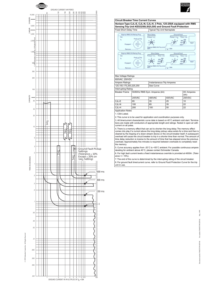
Circuit Breaker Time/Current Curves (Ground Current) ➀
Circuit Breaker Time Current Curves
®
K-Frame
Circuit
Breakers
Series CType
Horizon
CJL-E,
CJL-N,
CJL-H, 3 Pole, 125-250A equipped with RMS
Equipped With Type KES Digitrip RMS 310 Trip Units
Sensing
TripFault
Unit KES3250LSG/LSIG
and Ground Fault Protection
For Ground
Protection
Fixed Short Delay Time
2,000
Digitrip RMS 310 Rating Plug
Cat.
Push to Trip
In
Engaged
Digitrip RMS 310 Rating Plug
300
Engaged
Max Voltage Ratings
Remove
1 MINUTE
100
50
30
1xIG
20
4xIG
3xIG
10
5
3
Ground Fault Pickup
Settings
(Tolerance ± 10%
Except ± 20% on
1xIG Setting)
2xIG
5xIG
2
1
3
2
1
4
3
2
5
6
7
8
5
Time • ms
300
150
INST
500
TEST
Ground Fault
Time • ms
200
100
INST
4
Ig = 50A
Short Delay
Push to Trip
In
Ground Fault
Pickup • x Ig
6
7
8
Pickup • x Ir
Cat.
200
5
Digitrip RMS 310 Trip Unit
40oC
Remove
500
Short Delay
Pickup • x Ir
4
3
2
1,000
TIME IN SECONDS
Typical Trip Unit Nameplate
Type Digitrip RMS 310 Trip Unit for use with Circuit Breaker Types KD, HKD, KDC, CKD, and
CHKD
For use with Trip Unit Catalog Numbers
KES3250LSG
KES3250LSIG
3,000
© 1999 Schneider Canada Inc. All Rights Reserved
1 HOUR
5,000
300
Digitrip RMS 310 Trip Unit
40oC
Pickup • x Ig
3
2
1
4
5
Time • ms
300
150
INST
500
TEST
Ig = 50A
600VAC, 250VDC
Ampere
Ratings
Instantaneous Trip Amperes
Notes
Curve accuracy applies from –20°C to See
+55°CCurve
ambient. For possible continuous
125,150,175,200,225,250
ampere derating for ambient above 40°C, refer to Cutler-Hammer.
Interrupting Rating
Digitrip RMS
310 trip
units are
suitable
functional
field testing with test kit
Breaker
Frame
50/60Hz
RMS
Sym.for
Amperes
(kA)
DC Amperes
Cat. No. STK2. For field testing using primary injection methods, follow NEMA
(kA)
publication AB-4-1991.
240VAC
480VAC
600VAC
250VDC
curves see SC-5640-93,
SC-5641-93,
➀ For phase time/current
CJL-E
65
35
25 SC-5646-93, or10
SC-5647-93.
CJL-N
100
65
35
22
CJL-H
200
100
50
22
Application Notes
1. CSA Listed.
2. This curve is to be used for application and coordination purposes only.
3. All time/current characteristic curve data is based on 40˚C ambient cold start. Terminations are made with conductors of appropriate length and ratings. Tested in open air with
current on all poles.
4. There is a memory effect that can act to shorten the long delay. The memory effect
comes into play if a current above the long delay pickup value exists for a time and then is
cleared by the tripping of a down stream device or the circuit breaker itself. A subsequent
overload will cause the circuit breaker to trip in a shorter time than normal. The amount of
time delay reduction is inverse to the amount of time that has elapsed since the previous
overload. Approximately five minutes is required between overloads to completely reset
the memory.
5. Curve accuracy applies from -20˚C to +55˚C ambient. For possible continuous ampere
derating for ambient above 40˚C, please contact Schneider Canada.
6. For high fault current levels a fixed instantaneous override is provided at 4000A (Tolerance +/- 15%).
7. The end of the curve is determined by the interrupting rating of the circuit breaker.
8. For ground fault time/current curve, refer to Ground Fault Protection Curve for the trip
unit in use.
500 ms
.5
300 ms
.3
.2
150 ms
.1
May, 1999
I
Set number F0600TC9902EP R0
.05
.03
.01
Document number F0602TC9914EP R0
© 1999 Schneider Canada Inc. All Rights Reserved
.02
.005
.003
.002
.001
1
2
3
4
5
6
7 8 910
GROUND CURRENT-IN MULTIPLES OF Ig = 50A
100


