GE Energy
Evaluation Board Guide
DLynxTM Series Evaluation Board Documentation
The DLynxTM series evaluation board (DLYNX_PICO_MICRO_EVAL) is available in 2 formats:
• Single Footprint- supporting MDT/MVT040, UDT/UVT020, PVX003/006/012
• Dual layout of the PicoDLynxTM and the MicroDLynxTM series of modules – supporting PDT003/006/012 and
UDT/UVT020
Board comes with an assembled module. The specific combination of module and the board can be ordered through your
sales representative. PDT modules can be provided on single footprint boards as well
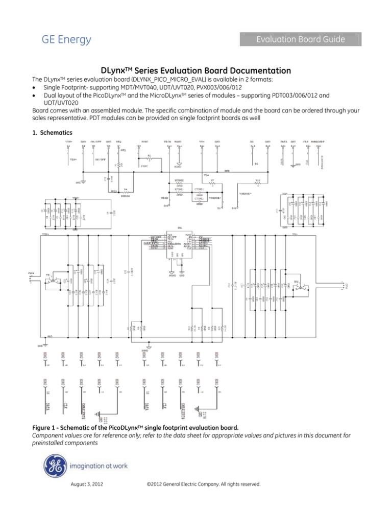
1. Schematics
Figure 1 - Schematic of the PicoDLynxTM single footprint evaluation board.
Component values are for reference only; refer to the data sheet for appropriate values and pictures in this document for
preinstalled components
August 3, 2012
©2012 General Electric Company. All rights reserved.
GE Energy
Evaluation Board Guide
Analog and Digital DLynxTM: Non-Isolated DC-DC Power Modules
3A to 40A Output Current converters
Figure 2 - Schematic of the MicroDLynxTM single footprint evaluation board.
Component values are for reference only; refer to the data sheet for appropriate values and pictures in this document for
preinstalled component
August 3, 2012
©2012 General Electric Company. All rights reserved.
Page 2
GE Energy
Evaluation Board Guide
Analog and Digital DLynxTM: Non-Isolated DC-DC Power Modules
3A to 40A Output Current converters
Figure 3 - Schematic of the MegaDLynxTM single footprint evaluation board.
Component values are for reference only; refer to the data sheet for appropriate values and pictures in this document for
preinstalled components
August 3, 2012
©2012 General Electric Company. All rights reserved.
Page 3
GE Energy
Evaluation Board Guide
Analog and Digital DLynxTM: Non-Isolated DC-DC Power Modules
3A to 40A Output Current converters
Dual layouts on the same board also serve as an example for applications where dual layouts may be desirable, e.g.
when the required output current is uncertain and there is an advantage in either adding a higher or lower power
capability through a dual layout.
Figure 4 shows the schematic of the PicoDLynxTM/MicroDLynxTM evaluation board.
Figure 4. Schematic for the Dual Layout PicoDLynxTM/MicroDLynxTM Evaluation board.
Component values are for reference only; refer to the data sheet for appropriate values and pictures in this document for
preinstalled components
August 3, 2012
©2012 General Electric Company. All rights reserved.
Page 4
GE Energy
Evaluation Board Guide
Analog and Digital DLynxTM: Non-Isolated DC-DC Power Modules
3A to 40A Output Current converters
2. Physical Description
An annotated photograph of the PicoDLynxTM, MicroDLynxTM and MegaDLynxTM single footprint evaluation board is shown
in Figs. 5, 6 and 7 below. The arrows indicate locations of various components.
Pre-Installed components for the PicoDLynxTM - Trim resistor R6, input filtering [C22 (0.047uF,16V), C25(22uF,16V),
C26,(22uF,16V), C38(470uF,16V)], Output filtering [C34(0.047uF,16V), C27(22μF,16V)], RSENSE resistors, R7 & R10 = 0 Ohms, R6
=20K and some test points.
On/Off Switch
Test Point (E5)
PG
Test Point (E14)
VOUT
Scope Probe socket
(TP2)
COUT
VOUT
Monitor (E12)
VIN
Monitor (E3)
CIN
VIN
Scope Probe socket
(TP1)
RTRIM#
(R6(20k))
RTUNE
(RT1/RT2)
CTUNE
(CT1/CT2)
RTRIM Test Points*
(E10 & E16)
Figure 5. Power and Analog Signal Interface for the PVX003/006/012 Eval Board
Caution! Before applying power, make sure that the externally installed capacitors (input & output) have appropriate
voltage and polarity ratings based on the application.
Notes:
# Module can be trimmed either by soldering fixed resistor(s) @ R6 or by attaching a potentiometer/resistor between test
points E10 and E16.
August 3, 2012
©2012 General Electric Company. All rights reserved.
Page 5
GE Energy
Evaluation Board Guide
Analog and Digital DLynxTM: Non-Isolated DC-DC Power Modules
3A to 40A Output Current converters
Pre-Installed components for the MicroDLynxTM - Input filtering [C25 (0.047uF,16V), C22(22uF,16V), C26,(22uF,16V),
C38(470uF,16V)], Output filtering [C34(0.047uF,16V), C27, C32 (47μF,6.3V)], RSENSE resistors, R7 & R10 = 0 Ohms, Trim R5 =20K,
Address R15=54.9K, R14=36.5K and some test points.
10-Pin Ribbon Cable to USB Interface Adaptor or
Second Eval Board
HDR1**
ADDR0*
HDR2**
(R9/R15)
RSYNCH
(R2=0)
VIN
Monitor (E3)
ADDR1*
RTRIM#
(R8/R14)
R5(20k)
RTUNE
(RT1/RT2)
CSEQ
(C21)
VOUT
Monitor (E12)
RSEQ
(R1 & R4)
VIN
Scope Probe socket
(TP1)
CIN
Sync Signal
Test point (E9)
RTRIM Test Point*
(E35)
VOUT
CTUNE
(CT1/CT2) Scope Probe socket
(TP2)
On/Off Switch
Test Point (E5)
PG
Test Point (E14)
Sequencing
Test Point (E7)
Figure 6. Power and Analog Signal Interface for the UDT/UVT020 Eval Board
Caution! Before applying power, make sure that the externally installed capacitors (input & output) have appropriate
voltage and polarity ratings based on the application.
Notes:
# Module can be trimmed either by soldering a different fixed resistor(s) @ R5 or by attaching a potentiometer/resistor
between test points E11 and E35.
August 3, 2012
©2012 General Electric Company. All rights reserved.
Page 6
GE Energy
Evaluation Board Guide
Analog and Digital DLynxTM: Non-Isolated DC-DC Power Modules
3A to 40A Output Current converters
Pre-Installed components for the MegaDLynxTM - Input filtering [C25 (0.047uF,16V), C2,C8,C22,C26,(22uF,16V), C38(470uF,16V)],
Output filtering [C34(0.047uF,16V), (6x47μF,6.3V)], RSENSE resistors, R7 & R10 = 0 Ohms, Trim R5 =20K, Address R15=54.9K,
R14=36.5K and some test points.
10-Pin Ribbon Cable to USB Interface
Adaptor or Second Eval Board
HDR2**
ADDR1*
(R8/R14)
VIN
Monitor (E3)
VIN
Scope Probe socket
(TP1)
ADDR0*
(R9/R15)
RTRIM#
R5(20k)
RTUNE
(RT1/RT2)
RSYNCH
(R2=0)
CIN
PG
Test Point (E14)
CTUNE
On/Off Switch
Test Point (E5) (CT1/CT2)
Sync Signal
Test point (E9)
VOUT
Monitor (E12)
RSEQ
(R1 & R4)
Sequencing
Test Point (E7)
CSEQ
(C21)
VOUT
Scope Probe socket
(TP2)
HDR1**
Figure 7. Power and Analog Signal Interface for the MDT/MVT040 Eval Board
Caution! Before applying power, make sure that the externally installed capacitors (input & output) have appropriate
voltage and polarity ratings based on the application.
Notes:
# Module can be trimmed either by soldering a different fixed resistor(s) @ R5 or by attaching a potentiometer/resistor
between test points E10 and E11.
August 3, 2012
©2012 General Electric Company. All rights reserved.
Page 7
GE Energy
Evaluation Board Guide
Analog and Digital DLynxTM: Non-Isolated DC-DC Power Modules
3A to 40A Output Current converters
An annotated photograph of the Dual Layout PicoDLynxTM/MicroDLynxTM evaluation board is shown in Figs. 8, 9 and 10
below. The minimum set of external components consists of the trim resistor R5/R6, input filtering (C7, C8 = 2 x 22μF/16V
ceramic capacitors are recommended as a minimum and one 470uF/16V electrolytic (C3) for bench testing. C3, C7 & C8
come pre-assembled on the board) and some modest amount of output filtering 22μF (minimum) ceramic (C11=22uF/16V
pre-assembled on the board). Additionally, the following components are preinstalled:
RSENSE resistors, R7 & R10 = 0 Ohms, RSYNCH resistor, R11=10K, RTRIM =20K, Address R15=54.9K, R14=36.5K
On/Off Switch
PG
Test Point (E5)
Test Point (E14)
RTUNE
(RT1/RT2)
VOUT
Scope Probe socket
(TP2)
Sync Signal
Test point (E9) Sequencing **
CTUNE
VOUT
Test Point (E7)
(CT1/CT2)
Monitor (E12)
COUT
VIN
Monitor (E3)
CIN
(C3 to C7)
VIN
Scope Probe socket
(TP1)
RSYNCH
(R11=10K))
JMP1**
For
Sequencing
RSEQ**
(R1 & R4)
RTRIM*
(R5/R6(20k))
ADDR1*
RTRIM
(R14) Test Points*
(E10)
ADDR0*
(R15)
Figure 8. Power and Analog Signal Interface for the Dual Layout PDT012 Eval Board
Caution! Before applying power, make sure that the externally installed capacitors (input & output) have appropriate
voltage and polarity ratings based on the application.
Notes:
* Module can be trimmed either by soldering fixed resistor(s) @ R5/R6 or by attaching a potentiometer/resistor between
test points E10 and E11.
** Place Shorting Jumper (JMP1) on the left two pins (as shown) when NOT testing for sequencing (SEQ pin open). When
testing for Sequencing, place JMP1 on the right two pins and select/install RSEQ resistors, R1 & R4. For further details see
the module’s data sheet and Application Note AN04-008 “Application Guidelines for Non-Isolated Converters: Guidelines
for Sequencing of Multiple Modules”.
August 3, 2012
©2012 General Electric Company. All rights reserved.
Page 8
GE Energy
Evaluation Board Guide
Analog and Digital DLynxTM: Non-Isolated DC-DC Power Modules
3A to 40A Output Current converters
The minimum set of external components consists of the trim resistor R5/R6, input filtering (C7, C8 = 2 x 22μF/16V
ceramic capacitors are recommended as a minimum and one 470uF/16V electrolytic (C3) for bench testing. C3, C7 & C8
come pre-assembled on the board) and some modest amount of output filtering 22μF (minimum) ceramic (C11=22uF/16V
pre-assembled on the board). Additionally, the following components are preinstalled:
RSENSE resistors, R7 & R10 = 0 Ohms, RSYNCH resistor, R11=10K, RTRIM =20K, Address R15=54.9K, R14=36.5K
Sync Signal
Test point (E9)
PG
Test Point (E14)
On/Off Switch
Test Point (E5)
RTUNE
(RT1/RT2)
CTUNE
(CT1/CT2)
VOUT
Scope Probe socket
(TP2)
Sequencing **
Test Point (E7)
VOUT
Monitor (E12)
COUT
VIN
Monitor (E3)
CIN
(C3 to C7)
VIN
Scope Probe socket
(TP1)
RSYNCH
(R11=10K))
JMP1**
For
Sequencing
RSEQ**
(R1 & R4)
RTRIM*
(R5/R6(20k))
RTRIM
ADDR1*
(R14) Test Points*
(E10)
ADDR0*
(R15)
Figure 9. Power and Analog Signal Interface for the Dual Layout UDT020 Eval Board
Caution! Before applying power, make sure that the externally installed capacitors (input & output) have appropriate
voltage and polarity ratings based on the application.
Notes:
* Module can be trimmed either by soldering fixed resistor(s) @ R5/R6 or by attaching a potentiometer/resistor between
test points E10 and E11.
** Place Shorting Jumper (JMP1) on the left two pins (as shown) when NOT testing for sequencing (SEQ pin open). When
testing for Sequencing, place JMP1 on the right two pins and select/install RSEQ resistors, R1 & R4. For further details see
the module’s data sheet and Application Note AN04-008 “Application Guidelines for Non-Isolated Converters: Guidelines
for Sequencing of Multiple Modules”.
August 3, 2012
©2012 General Electric Company. All rights reserved.
Page 9
GE Energy
Evaluation Board Guide
Analog and Digital DLynxTM: Non-Isolated DC-DC Power Modules
3A to 40A Output Current converters
Digital Interface: The components and test points highlighted in the following figure can be used to evaluate PMBus
Digital Interface functionality for the Digital DLynxTM modules.
HDR1**
HDR2**
10-Pin Ribbon Cable
to USB Interface Adaptor
or
Second Eval Board
ADDR0*
(R9/R15)
CLK
DATA
Test Point Test Point
(E31)
(E31)
SMB ALERT
Test Point
(E32)
ADDR1*
(R8/R14)
Figure10. PMBus Digital Interface for the Dual Layout Board
Notes:
* The digital DLynx Module can be assigned a specific address by connecting resistors (R9/R15) from the ADDR0 pin to
GND and resistors (R8/R14) from the AADR1 pin to GND. The evaluation board comes with preinstalled ADDR1 resistor,
R14=36.5K and ADDR0 resistor, R15=54.9K as an example. These values correspond to Octal digits “3 4” equivalent to HEX
number “1C” (equivalent to 28 decimal). Please refer to the data sheet for additional details.
** HDR1/HDR2 allow the unit on the Eval board to interface (via 10 pin Ribbon Cable) with another unit on a different Eval
Board and/or to Lineage Power’s “USB Interface Adapter” module in order for multiple modules to be controlled by the
GUI. For further details, please refer to the Lineage Power document, “Digital Power InsightTM User Manual”.
Note1: The red wire on the ribbon cable should be aligned to Pin 1 (left side) of the HDR1 or HDR2 connectors.
Note2: Headers and Ribbon Cable Assembly details:
Part Description (HDR1 & HDR2): 10-Pin Dual Row Male Pin Header, SMT
e.g. FCI P/N: 95157-210 (Digi-Key P/N: 95157-210-ND) or Molex P/N: 0015910100
Part Description: IDC Ribbon Cable Assembly
e.g.: 3M P/N: M3DDA-1018J (Digi-Key P/N: M3DDA-1018J-ND) or Molex P/N: 111062-022
August 3, 2012
©2012 General Electric Company. All rights reserved.
Page 10
GE Energy
Evaluation Board Guide
Analog and Digital DLynxTM: Non-Isolated DC-DC Power Modules
3A to 40A Output Current converters
Dual Layout 12A/6A/3A Analog PicoDLynxTM :
PG
Test Point (E14)
VIN
Monitor (E3)
On/Off Switch
Test Point (E5)
VIN
Scope Probe socket
(TP1)
RTUNE
(RT1/RT2)
CTUNE
(CT1/CT2)
CIN
(C3 to C7)
VOUT
Scope Probe socket
VOUT
(TP2)
Monitor (E12)
RTRIM*
(R5/R6)
RTRIM Test Point*
(E10)
Figure 11. Analog Dual Layout 12A PicoDLynx (PVX012A0X) Interface
Note1: Place Shorting Jumper (JMP2) on the bottom two pins as shown (SGND and GND will be shorted) or place RTRIM
resistors on pads identified as R12 & R13. (Other versions of this evaluation board may not have R12 & R13 pads). For
further reference refer to Fig 4
Contact Us
For more information, call us at
USA/Canada:
+1 888 546 3243, or +1 972 244 9288
Asia-Pacific:
+86.021.54279977*808
Europe, Middle-East and Africa:
+49.89.74423-206
India:
+91.80.28411633
www.ge.com/powerelectronics
August 3, 2012
©2012 General Electric Company. All rights reserved.
Version 0.33


