Driving Analog Stimuli from
a UVM testbench
Satvika Challa, Amlan Chakrabarti
AMD India Pvt Ltd, Bangalore
INTRODUCTION
PROBLEM STATEMENT & PRIOR WORK
Design of high-performance complex SoCs in low power envelopes is causing
both analog and digital designs to increase in complexity. This intensifies the need for
more robust verification of these designs. Many methods are adopted in the industry
for verifying digital designs. Constrained random verification helps in creating lots of
scenarios that help to uncover bugs in the early stages of digital design development.
Analog blocks such as ADCs and voltage regulators need a similar kind of verification
environment to ensure the quality of design. Conventional circuit simulations fail to
address this need as the driven stimulus is static in nature. Effects of noise on supply
and abrupt changes in voltage sources have to be observed to evaluate the
performance of the design. Self-checking and highly automated testbenches
generating analog stimuli are required for this purpose.
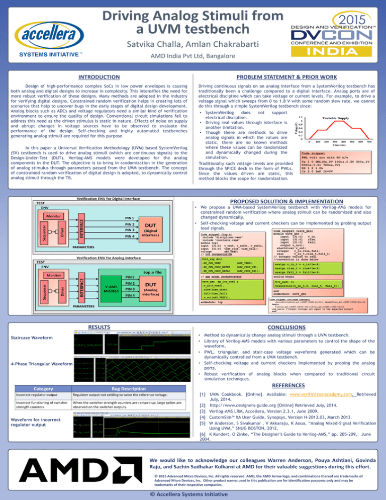
Driving continuous signals on an analog interface from a SystemVerilog testbench has
traditionally been a challenge compared to a digital interface. Analog ports are of
electrical discipline which can take voltage or current levels. For example, to drive a
voltage signal which sweeps from 0 to 1.8 V with some random slew rate, we cannot
do this through a simple SystemVerilog testbench since:
In this paper a Universal Verification Methodology (UVM) based SystemVerilog
(SV) testbench is used to drive analog stimuli (which are continuous signals) to the
Design-Under-Test (DUT). Verilog-AMS models were developed for the analog
components in the DUT. The objective is to bring in randomization in the generation
of analog stimulus through parameters passed from the UVM testbench. The concept
of constrained random verification of digital design is adopted, to dynamically control
analog stimuli through the TB.
• SystemVerilog
does
not
support
electrical discipline.
• Driving real values through interface is
another limitation.
• Though there are methods to drive
analog signals in which the values are
static, there are no known methods
where these values can be randomized
and dynamically changed during the
simulation.
Traditionally such voltage levels are provided
through the SPICE deck in the form of PWLs.
Since the values driven are static, this
method blocks the scope for randomization.
PROPOSED SOLUTION & IMPLEMENTATION
• We propose a UVM-based SystemVerilog testbench with Verilog-AMS models for
constrained random verification where analog stimuli can be randomized and also
changed dynamically.
• Self-checking voltage and current checkers can be implemented by probing output
load signals.
RESULTS
CONCLUSIONS
• Method to dynamically change analog stimuli through a UVM testbench.
• Library of Verilog-AMS models with various parameters to control the shape of the
waveform.
• PWL, triangular, and stair-case voltage waveforms generated which can be
dynamically controlled from a UVM testbench.
• Self-checking voltage and current checkers implemented by probing the analog
ports.
• Robust verification of analog blocks when compared to traditional circuit
simulation techniques.
Staircase Waveform
4-Phase Triangular Waveform
Category
REFERENCES
Bug Description
Incorrect regulator output
Regulator output not settling to twice the reference voltage.
Incorrect functioning of switcher
strength counters
When the switcher strength counters are ramped up, large spikes are
observed on the switcher outputs.
Waveform for incorrect
regulator output
[1] UVM Cookbook. [Online]. Available: www.verificationacademy.com. Retrieved
July, 2014.
[2] http://www.designers-guide.org [Online] Retrieved July, 2014.
[3] Verilog-AMS LRM, Accellera, Version 2.3.1, June 2009.
[4] CustomSim™ XA User Guide, Synopsys, Version H-2013.03, March 2013.
[5] W Anderson, S Sivakumar , V Akkaraju, K Aoua, “Analog Mixed-Signal Verification
Using UVM,” SNUG BOSTON, 2012.
[6] K Kundert, O Zinke, “The Designer’s Guide to Verilog-AMS,” pp. 205-209, June
2004.
We would like to acknowledge our colleagues Warren Anderson, Pouya Ashtiani, Govinda
Raju, and Sachin Sudhakar Kulkarni at AMD for their valuable suggestions during this effort.
© 2015 Advanced Micro Devices, Inc. All rights reserved. AMD, the AMD Arrow logo, and combinations thereof are trademarks of
Advanced Micro Devices, Inc. Other product names used in this publication are for identification purposes only and may be
trademarks of their respective companies.
© Accellera Systems Initiative


