8800DB0408
October 2004
Raleigh, NC, USA
Data Bulletin
Altivar® Adjustable Speed Drives
Energy Savings for Pumps
Restricted to Company Personnel
INTRODUCTION
Figure 1:
In most facilities, centrifugal pumps run at fixed speeds, and fluid-flow rates
are varied by automatic valves or other mechanical devices. Being able to
adjust a pump’s speed to achieve a desired flow rate can result in significant
energy savings.
Pump Speed Adjustments
100% Load
at 100%
Speed
% Torque and Horsepower
100
At 50% Speed:
• Torque = 25%
of full load
torque
• HP = 12.5% of
full speed brake
horsepower
Flow
Volume
Input Power
Head
Original equipment manufacturers (OEM) generally size centrifugal pumps
to handle peak volume requirements that typically occur for short periods.
As a result, centrifugal pumps mostly operate at reduced volumes.
25
12.5
0
50
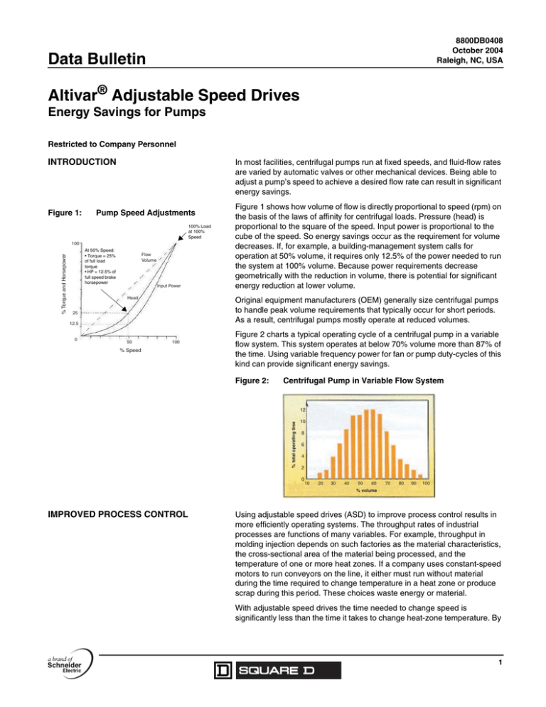
Figure 1 shows how volume of flow is directly proportional to speed (rpm) on
the basis of the laws of affinity for centrifugal loads. Pressure (head) is
proportional to the square of the speed. Input power is proportional to the
cube of the speed. So energy savings occur as the requirement for volume
decreases. If, for example, a building-management system calls for
operation at 50% volume, it requires only 12.5% of the power needed to run
the system at 100% volume. Because power requirements decrease
geometrically with the reduction in volume, there is potential for significant
energy reduction at lower volume.
100
% Speed
Figure 2 charts a typical operating cycle of a centrifugal pump in a variable
flow system. This system operates at below 70% volume more than 87% of
the time. Using variable frequency power for fan or pump duty-cycles of this
kind can provide significant energy savings.
Figure 2:
Centrifugal Pump in Variable Flow System
% total operating time
12
10
8
6
4
2
0
10
20
30
40
50
60
70
80
90
100
% volume
IMPROVED PROCESS CONTROL
Using adjustable speed drives (ASD) to improve process control results in
more efficiently operating systems. The throughput rates of industrial
processes are functions of many variables. For example, throughput in
molding injection depends on such factories as the material characteristics,
the cross-sectional area of the material being processed, and the
temperature of one or more heat zones. If a company uses constant-speed
motors to run conveyors on the line, it either must run without material
during the time required to change temperature in a heat zone or produce
scrap during this period. These choices waste energy or material.
With adjustable speed drives the time needed to change speed is
significantly less than the time it takes to change heat-zone temperature. By
1
Altivar® Adjustable Speed Drives
Energy Savings for Pumps
8800DB0408
October 2004
adjusting the material flow continuously to match the heat zone conditions,
a company can operate continuously. The results are less energy use and
less scrap.
REDUCED MECHANICAL STRESS:
SOFT STARTING
While most engineers select adjustable speed drives for energy savings and
process improvements, these drives also reduce mechanical stress on
process systems through reduced voltage starting. Starting a motor on line
power increases stress on the mechanical system causing belts to slip and
squeal, high pressure develops in pipes and ducts, and chains jump.
Reduced-voltage and reduced-frequency starting decreases this
mechanical stress. Adjustable speed drives vary the output voltage along
with output frequency to control a motor's torque and speed. This control
results in a soft start as the motor's speed accelerates based on a preprogrammed rate. Acceleration time in most adjustable speed drives can be
varied from 5 to 360 seconds. In short, variable-speed drives inherently offer
soft starts.
IMPROVED ELECTRICAL SYSTEM
POWER FACTORS
OEMs are concerned about how adjustable speed drives affect their
facility's power factor because many utility companies penalize facilities with
poor power factors. Figure 3 shows a typical power factor triangle.
Figure 3:
The size of a building's power distribution system is represented in kVA. The
useful work performed by motors and other electrical equipment wired to the
power system is measured in kW. It's useful to think of power factor as the
measure of a device's efficiency in converting power consumed (kVA) to
useful work (kW). Cos Θ represents the power factor. See Θ (or inverse
cos Θ) gives the angular displacement in the power factor triangle.
Typical Power Factor Triangle
kW
Power factor = cos θ = ____
kVA
kVA
kVAr
θ
kW
Schneider Electric USA
8001 Highway 64 East
Knightdale, NC 27545 USA
1-888-SquareD (1-888-778-2733)
www.us.SquareD.com
To function, all induction machines, including motors or active current,
require magnetizing power. A machine's kW and power factor determine the
magnetizing power (the vertical segment of the power factor triangle),
labeled kVAr (kilovolt-ampere reactive).
Electrical equipment should be installed, operated, serviced, and maintained only by
qualified personnel. No responsibility is assumed by Schneider Electric for any
consequences arising out of the use of this material.
© 2004 Schneider Electric All Rights Reserved


