MDT-8RJ/16RJ Telep 12382 south gateway park place, 700, draper
advertisement

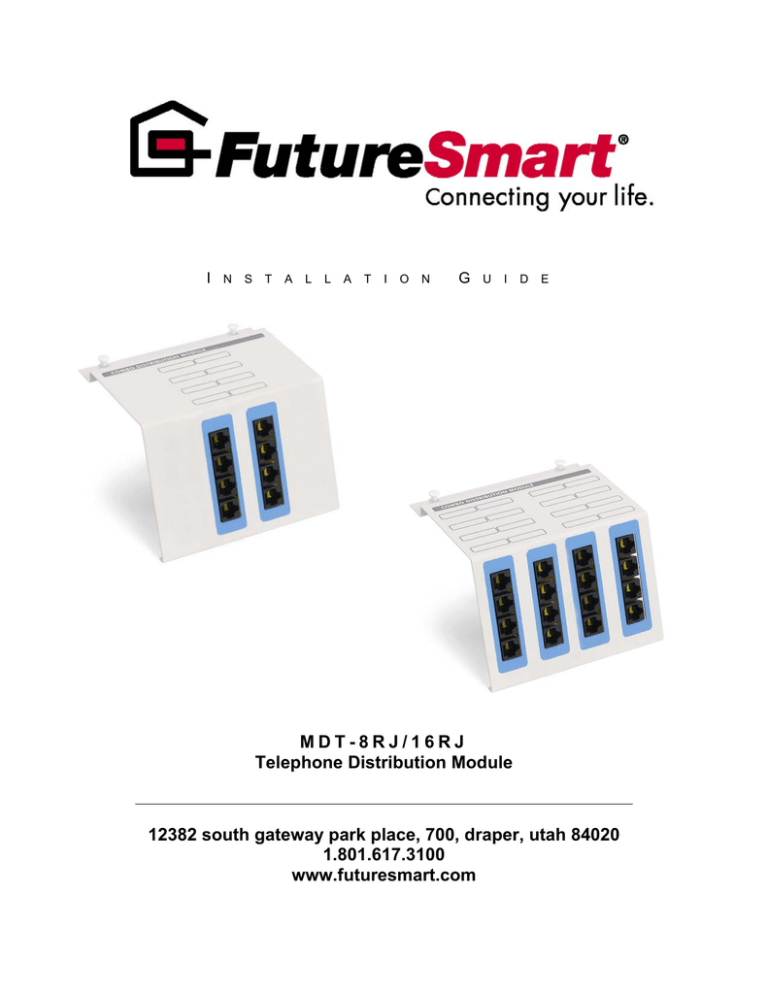
I N S T A L L A T I O N G U I D E MDT-8RJ/16RJ Telephone Distribution Module 12382 south gateway park place, 700, draper, utah 84020 1.801.617.3100 www.futuresmart.com FutureSmart MDT-8RJ/16RJ Telephone Distribution Module Installation Guide The FutureSmart Telephone Distribution Module provides distribution of 4 incoming telephone lines to 16 locations (MDT-16RJ or 8 locations for MDT8RJ). Please be sure to review this installation guide carefully prior to installation. Installing the Telephone Distribution Module 1. Run a CAT5e twisted pair cable from the NID (network interface device). This is a box installed by the phone company on the side of the home to the telephone distribution module. 2. Identify the CAT5e wire running from the telephone module to each of the rooms (premise wiring) and remove 2 inches of the outer PVC jacket from the end, exposing the 4 pairs. Terminate these wires with RJ45 Modular Telephone Plugs. 3. Terminate the incoming CAT5e wire from the NID to the 110-style punch down blocks on the rear of the module. The MDT-16RJ will have two connections and the MDT-8RJ will have one. If you are also connecting a security system, see the section “Installing the module with a security system”. RJ31X Incoming Cat5e 110 termination Figure 1 4. Connect the terminated CAT5e premise wire (the wires running from the CHMDT16RJ to the rooms) to any of the 16 RJ45 outputs on the front of the CHMDT16RJ module. 2 FutureSmart MDT-8RJ/16RJ Telephone Distribution Module Installation Guide Installing the module with a Security System 1. Run a CAT5e twisted pair cable from the NID (network interface device). This is a box installed by the phone company on the side of the home to the module. 2. Identify the CAT5e wire running from the module to each of the rooms (premise wiring) and remove 2 inches of the outer PVC jacket from the end, exposing the 4 pairs. Terminate these wires with RJ45 Modular Telephone Plugs. 3. Terminate the incoming CAT5e wire from the NID to the first 110 style punch down block on the rear of the module, and use a CAT5e patch cord to patch from the security system to the RJ31X port on the rear of the module. RJ31 X Security Interface Port Patch Cord from the Security System Incoming CAT5e wire from the NID 4. Install a small CAT5e jumper on the front of the module connecting the two PC boards (Only with the MDT-16RJ). 5. Connect the terminated CAT5e premise wire (the wires running from the module to the rooms) to any of the remaining 14 RJ45 outputs on the front of the module. 3 FutureSmart MDT-8RJ/16RJ Telephone Distribution Module Installation Guide This termination method makes line one the primary line on the first PC board, and line two the primary line on the second PC board. This termination method makes lines 1 and 2 available as the first and second lines on 8 outputs, and lines 3 and 4 available as the first and second line on the other 8 outputs. 4


