Electrical
temperature measurement
Tubeskin thermocouple assembly
Model TC59-X
WIKA data sheet TE 65.57
XTRACTO-PAD
Applications
■■ Chemical industry
■■ Superheated steam applications
■■ Refineries
■■ Heating furnaces and high-performance boilers
■■ Heat exchangers
Special features
■■ Removable thermocouple design
■■ Patented moldable heat shield
■■ Application ranges from 0 ... 1,260 °C (32 ... 2,300 °F)
■■ Flexible sheathed cable, mineral-insulated internal leads
■■ High mechanical strength, shock resistant
Description
The XTRACTO-PAD enables the measurement of a tube
within a combustion furnace to be measured accurately.
The XTRACTO-PAD is a product developed by Gayesco
International Inc. The expertise, knowledge and products of
Gayesco are now part of the WIKA Group.
The XTRACTO-PAD is a thermocouple design utilizing
a guide channel and patented heat shield. A removable
contoured thermocouple sensor made from mineral-insulated
cable (sheathed cable) is installed in the guide channel
and heat shield. It consists of a metal outer sheath, which
contains the insulated internal leads, compressed within a
high-density ceramic composition. The internal leads are
made from thermo material. The material of the outer sheath
can be selected to match the application. At one end of the
sheathed cable, the internal leads are welded together to
form an insulated (ungrounded) or non-insulated (grounded)
measuring point.
This unique thermocouple design allows for weldable parts
(guide channel, heat shield, and tube clips) to be installed
by the manufacturer of the heater / boiler or even by the tube
manufacturer in the case of specialty furnace tubes.
WIKA data sheet TE 65.57 ∙ 09/2015
Data sheets showing similar products:
Tubeskin thermocouple assembly; model TC59-R; see data sheet TE 65.56
Tubeskin thermocouple assembly; model TC59-W; see data sheet TE 65.58
Tubeskin thermocouple assembly; model TC59-V; see data sheet TE 65.59
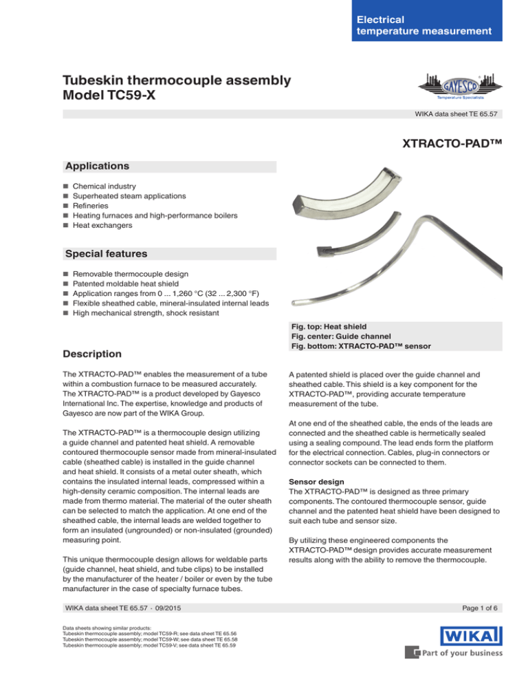
Fig. top: Heat shield
Fig. center: Guide channel
Fig. bottom: XTRACTO-PAD sensor
A patented shield is placed over the guide channel and
sheathed cable. This shield is a key component for the
XTRACTO-PAD, providing accurate temperature
measurement of the tube.
At one end of the sheathed cable, the ends of the leads are
connected and the sheathed cable is hermetically sealed
using a sealing compound. The lead ends form the platform
for the electrical connection. Cables, plug-in connectors or
connector sockets can be connected to them.
Sensor design
The XTRACTO-PAD is designed as three primary
components. The contoured thermocouple sensor, guide
channel and the patented heat shield have been designed to
suit each tube and sensor size.
By utilizing these engineered components the
XTRACTO-PAD design provides accurate measurement
results along with the ability to remove the thermocouple.
Page 1 of 6
Sensor
Sensor types
Type
Recommended max. operating temperature
K
1,200 °C (2,192 °F)
1,260 °C (2,300 °F)
750 °C (1,382 °F)
760 °C (1,400 °F)
1,200 °C (2,192 °F)
1,260 °C (2,300 °F)
900 °C (1,652 °F)
870 °C (1,598 °F)
J
N
E
IEC 60584-1
Thermocouple
Type
Class
IEC 60584-1
ASTM E230
ASTM E230
1 and 2
Standard, special
J
1 and 2
Standard, special
1 and 2
Standard, special
E
1 and 2
Standard, special
K
N
Tolerance value
For the tolerance value of thermocouples, a cold junction
temperature of 0 °C has been taken as the basis.
When using a compensating cable or thermocouple cable,
an additional measuring error must be considered.
Sensor junction
The XTRACTO-PAD is supplied as an insulated
(ungrounded) or non-insulated (grounded) measuring point.
For detailed specifications for thermocouples, see Technical
information IN 00.23 at www.wika.com.
Mechanical design
Sensor
The XTRACTO-PAD sensor matches the curvature of
the tube size for installation. The contoured shape provides
easy insertion into the guide channel and provides intimate
contact with the tube being measured.
This in combination with proper tube clip location offers
accuracy and reliability in demanding applications.
Guide channel / weld-pad
The guide channel provides a strong welded connection on
three sides of the 19 mm x 19 mm (3/4" x 3/4") weld-pad.
The sensor can easily be removed/installed along this guide
channel. Special features of this channel ensure intimate
contact to the tube being measured.
Page 2 of 6
Heat shield
The patented XTRACTO-PAD shield and moldable
insulation is designed for high heat flux and/or difficult
applications; up to and including flame impingement.
Standard heat shield materials
■■ Stainless steel 1.4841 (310)
■■ 2.4816 (Inconel 600®)
Sheathed cable
The sheathed cable is flexible. The minimum bending radius
is five times the sheath diameter.
Sheath diameter
■■ 6.0 mm
■■ 6.4 mm (¼")
■■ 7.9 mm (5/16")
Other sheath diameters on request
XTRACTO-PAD and sheath materials
■■ Ni-alloy 2.4816 (Inconel 600)
- up to 1,200 °C / 2,192 °F (air)
- standard material for applications which require specific
corrosion resistance properties under exposure to high
temperatures, resistant to induced stress corrosion
cracking and pitting in media containing chloride
- highly resistant to halogens, chlorine, hydrogen chloride
- problematic applications in sulphurous fuels
■■ Steels
- up to 850 °C / 1,562 °F (air)
- good corrosion resistance with aggressive media as well
as steam and flue gases in chemical media
XTRACTO-PAD™
material
Resistance in
2.4665 (Hastelloy X®)
Medium
Stainless steel 1.4841 (310)
Medium
sulphurous maximum
ambient
temperature
2.4816 (Inconel 600®)
Stainless steel 1.4749 (446) 1)
Pyrosil D®
Haynes HR
160®
Stainless steel 1.4401 (316)
Low
1,150 °C (2,102 °F)
1,150 °C (2,102 °F)
1,150 °C (2,102 °F)
High
1,150 °C (2,102 °F)
Very high
1,250 °C (2,282 °F)
High
Medium
1,200 °C (2,192 °F)
850 °C (1,562 °F)
Other materials on request
1) Depending on design
WIKA data sheet TE 65.57 ∙ 09/2015
Design and electrical connection
XTRACTO-PAD thermocouples are classified into the following variants, depending on the nature of their electrical
connections:
Fixed connection (compression fitting) to the furnace
■■ Cable length 150 mm, other lengths on request
■■ Compensating cable type depending on the sensor type, PTFE-insulated
■■ The sealing from the process is performed by the compression fitting. It can be supplied in most common thread sizes.
■■ A connection head can be mounted directly to the neck or remotely.
Sliding connection (piston/spring) to the furnace
Spring-loaded style
Existing
Piston style
Existing
■■ Cable length to user specifications
■■ Number of leads depends on the number of sensors, lead ends bare
■■ Insulation (material / ambient temperature max.):
- PVC
- PTFE
- Fibreglass
105 °C (221 °F)
250 °C (482 °F)
400 °C (752 °F)
■■ A connection head can be mounted remotely.
WIKA data sheet TE 65.57 ∙ 09/2015
Page 3 of 6
Connection head
1/4000
7/8000
Model
Material
Cable entry 1)
Ingress protection
Cap
Surface finish 2)
1/4000 S
Stainless steel
½ NPT
IP 65
Screw cover
Blank
7/8000 W
Aluminium
½ NPT
IP 65
Screw cover
Blue, painted
7/8000 S
Stainless steel
½ NPT
IP 65
Screw cover
Blank
5/6000 F
Aluminium
3 x ½ NPT
IP 65
Screw cover
Blue, painted
1/4000 F
Aluminium
5/6000
½ NPT
IP 65
Screw cover
Blue, painted
1) Standard, others on request
2) RAL 5022
Field temperature transmitter (option)
Field temperature transmitter, model TIF50
As an alternative to the standard connection head, the
sensor can be fitted with an optional model TIF50 field
temperature transmitter.
A remote version for tube/surface mounting for the sensor
designs with connection cable is also possible. The field
temperature transmitter comprises a 4 ... 20 mA/HART®
protocol output and is equipped with an LCD indication
module.
Field temperature transmitter
Fig. left: model TIF50, head version
Fig. right: model TIF50, wall mounting
Page 4 of 6
WIKA data sheet TE 65.57 ∙ 09/2015
Transmitter (option)
Connection head
Transmitter model
A transmitter can be mounted directly into the connection
head.
1/4000
○
The following installation variants are thus possible:
7/8000
○ Mounted instead of terminal block
● Mounted within the cap of the connection head
– Mounting not possible
Model
T12
5/6000
Description
T12
T32
T53
○
○
○
○
○
○
Explosion protection
Digital transmitter, PC configurable
Optional
○
Data sheet
TE 12.03
T32
Digital transmitter,
Optional
TE 32.04
Digital transmitter FOUNDATION™ Fieldbus and PROFIBUS® PA
Standard
TE 53.01
TIF50
Digital field temperature transmitter, HART® protocol
Optional
TE 62.01
T53
HART®
protocol
○
Design and installation
Expansion loops
WIKA uses trained specialists to customise the temperature
measuring points to the application. These specialists
utilise best practices derived from scientific properties to
optimise the life and accuracy of the thermocouple. They
make suggestions to optimise the system for temperature,
movement, and burner firing.
Expansion loops should be designed to account for
maximum tube movement from startup position to operating
temperature. Loops should be designed in accordance with
allowable space available.
Some design considerations that can help determine
measuring points for the specific application in order to
choose the best suitable product:
Examples of expansion loops:
S-loop
■■ Material compatibility with furnace tube
■■ Heat transfer (radiation, convection, conduction)
■■ Junction (grounded, ungrounded)
■■ Thickness of the mineral-insulated cable (flexibility vs.
durability)
■■ Expansion loops (location and design)
■■ Flame impingement
■■ Furnace exit design options
Single coil
■■ Burner fuel (flue gas composition)
■■ Welding procedure (TIG, stick, temperature monitoring)
■■ Mounting (location, orientation)
■■ Operating vs. design temperatures
■■ Bending radius
■■ Path to furnace wall
Multiple coil
■■ Tube clips (location and routing)
■■ Connection head (material, location, approvals)
■■ Furnace design (burner locations)
Spiral loop
WIKA data sheet TE 65.57 ∙ 09/2015
Page 5 of 6
Electrical connection
Cable connection
Single thermocouple
Cable
Dual thermocouple
Colour coding of the wire ends see table
Single thermocouple
Dual thermocouple
3171966.01
Ceramic terminal block
Crastin terminal block
Single thermocouple
Dual thermocouple
+
+
-
-
-
+
Colour code of cable
■■ IEC 60584-3
Thermocouple type
Positive leg
Negative leg
J
Black
White
Violet
White
N
Pink
White
Thermocouple type
Positive leg
Negative leg
J
White
Red
Violet
Red
N
Orange
Red
K
The colour coding at the positive connection to the
instruments always decides the correlation of polarity and
connection terminal.
For the electrical connections of built-in temperature
transmitters as well as for pin assignment of the model TIF50
field temperature transmitter with digital indicator see the
corresponding data sheets or operating instructions.
E
■■ ASTM E230
K
E
Green
Yellow
White
Red
Accessories
Description
Tube half clips
Material: Stainless steel 310 or Inconel 600®
■■ MI cable ∅ 6.0 ... 6.4 mm (¼“)
■■ MI cable ∅ 7.9 mm (5/16")
Other materials on request
Ordering information
Model / Explosion protection / Connection head / Cable entry / Terminal block, transmitter / Design of thread / Measuring
element / Sensor type / Temperature range / Probe diameter / Pipe diameter / Materials / Thread size / Connection cable,
sheath / Lenghts N, W, A / Options
Page 6 of 6
WIKA data sheet TE 65.57 ∙ 09/2015
WIKA Alexander Wiegand SE & Co. KG
Alexander-Wiegand-Straße 30
63911 Klingenberg/Germany
Tel.
+49 9372 132-0
Fax
+49 9372 132-406
info@wika.de
www.wika.de
09/2015 EN
© 2015 WIKA Alexander Wiegand SE & Co. KG, all rights reserved.
The specifications given in this document represent the state of engineering at the time of publishing.
We reserve the right to make modifications to the specifications and materials.


