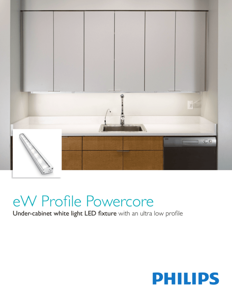
eW Profile Powercore
Under-cabinet white light LED fixture with an ultra low profile
eW Profile Powercore
Under-cabinet white light LED fixture with an ultra low profile
eW Profile Powercore is a direct line voltage, under-cabinet LED fixture for common task lighting and display
case applications. Available in 3000 K or 4000 K color temperatures, eW Profile Powercore is suitable for
new installations and retrofits requiring superior illumination quality and dramatic energy savings. With an
ultra-low-profile housing, three fixture lengths, versatile jumper options, and housing colors to match any
environment, eW Profile Powercore offers an unprecedented level of design flexibility and ease of use.
• Integrates patented Powercore technology —
Powercore rapidly, efficiently, and accurately
controls power output to fixtures directly from
line voltage, eliminating the need for external
power supplies. Contractor-friendly installation
dramatically simplifies installation and lowers total
system cost.
• Industry leading quality — eW Profile Powercore
offers long useful source life (up to 48,000
hours at 70% lumen maintenance). Optibin,
our proprietary binning optimization process,
guarantees uniformity and consistency of hue and
color temperature across LED sources, fixtures,
and manufacturing runs.
• Exceptional illumination performance — Meets
IESNA illumination intensity specifications
for optimal usability and safety in task lighting
applications. For commercial display purposes,
the 105° x 100° with 20° offset beam angle
provides designers with uniform beam quality
to develop visual interest and enhanced product
attractiveness.
• Dimming capability — Patented DIMand
technology offers smooth dimming capability with
select reverse-phase ELV-type dimmers.
• Energy cost savings — Consumes as little as 5.5
watts of energy per fixture, and can support
continuous runs of up to 50 ft (15.3 m). eW
Profile Powercore fixtures use 40% less energy
than comparable fluorescent sources, and 80% less
energy than incandescent sources. No off-state
power consumption increases energy savings.
• Versatile installation options — An ultra-lowprofile housing allows discreet under-cabinet
placement. Available 9.25 in, 19.25 in, and 39.25
in fixture lengths with multiple jumper cable and
connector options to accommodate nearly any
layout. UL rated for dry and damp environments.
• “Cool lighting” functionality — eW Profile
Powercore fixtures do not heat illuminated
surfaces, discharge infrared radiation, or emit
ultraviolet light.
• ENERGY STAR® qualified — As an ENERGY
STAR qualified LED luminaire (120 V), eW
Profile Powercore helps prevent greenhouse gas
emissions by meeting strict energy efficiency
guidelines set by the U.S. Environmental
Protection Agency and the U.S. Department of
Energy.
Superior Light
Output
eW Profile Powercore
produces highly
uniform white light
output of over 300
lumens per foot at both
3000 K and 4000 K
color temperatures.
2
eW Profile Powercore Product Guide
White Is the New White
White-light LED technology for general and task illumination is rapidly coming into
its own, driven by the imperatives of energy-efficiency and cost-effectiveness.
White-Light LED Fixtures for General Illumination
Philips Color Kinetics white light LED fixtures that bright, affordable, and flexible in
general lighting applications. By bringing high-quality white LED lighting to everyday
work, retail, and living spaces, Philips Color Kinetics continues to deliver on its
commitment to providing lighting solutions that improve people’s lives, protect the
environment, and surpass the limitations of traditional lighting sources.
Innovative and Energy Efficient Lighting for Task Areas
The advantages of innovative, energy-efficient white-light LED solutions are on
display in a high-end kitchen in a private residence in Cambridge, Massachusetts,
USA.
The homeowners wanted to create a hip and modern lighted environment without
sacrificing energy efficiency. The lighting designer selected a combination of LED
fixtures, including iColor Cove QLX for color-changing accent lighting and eW
Profile Powercore for task lighting above the kitchen’s generous counter space.
eW Profile Powercore offers high color rendering for superior visualization in the
task areas while helping to reduce the kitchen’s overall energy consumption by a
significant percentage over the previously installed conventional light sources.
eW Profile Powercore Product Guide 3
Photometrics
Photometric data is based on test results from an independent NIST traceable testing
lab. IES data is available at www.colorkinetics.com/support/ies.
eW Profile Powercore
9.25 in, 3000 K
Lumens
256
Efficacy
42.2 lm / W
Polar Candela Distribution
90º
Cd: 0
18
80º
37
70º
55
60º
73
92
50º
Illuminance at Distance
Candela Table
0.0
93
96
100
101
98
88
74
60
47
25
14
0
5
15
25
35
45
55
65
75
85
90
45.0
93
95
97
96
91
81
65
47
32
15
9
Center Beam fc
90.0 135.0 180.0
93
93
93
93
90
89
89
82
78
83
68
62
72
53
46
58
36
31
40
21
15
21
9
5
8
3
2
2
1
0
0
0
0
0.5 ft
1.0 ft
1.5 ft
2.0 ft
2.5 ft
3.0 ft
110
VA: 0º
10º
20º
- 0º H
30º
eW Profile Powercore
9.25 in, 4000 K
Lumens
Efficacy
262
41.9 lm / W
LUMENS
72
117
199
253
4
4
4
4
256
18
80º
37
70º
55
60º
73
92
50º
20º
30º
5.0 ft
15 fc
6.5 ft
6.3 ft
10 fc
7.8 ft
7.6 ft
Vert. Spread: 104.8º
Horiz. Spread: 103.1º
70
70 50 30 10
50
50 30 10
30
50 30 10
10
50 30 10
0
0
0
1
2
3
4
5
6
7
8
9
10
119119119119
108103 99 95
98 90 83 77
90 79 71 65
82 70 62 55
76 63 54 47
70 57 48 42
65 52 43 37
61 47 39 33
57 43 35 30
53 40 32 27
116116116116
105101 97 93
96 88 82 76
87 78 70 64
80 69 61 54
74 62 53 47
68 56 47 41
63 51 42 37
59 46 38 33
55 43 35 29
52 39 32 27
110110110
96 93 90
84 79 74
74 68 63
66 59 54
60 52 46
54 46 41
49 42 36
45 38 32
41 34 29
38 31 27
105105105
92 89 87
81 76 72
71 66 61
64 58 53
57 51 46
52 45 40
47 41 36
44 37 32
40 34 29
37 31 26
101101101
88 86 84
77 74 71
69 64 60
61 56 52
55 50 45
50 44 40
46 40 35
42 36 32
39 33 29
36 30 26
99
82
68
58
50
43
38
33
30
27
24
Illuminance at Distance
Candela Table
0
5
15
25
35
45
55
65
75
85
90
0.0
95
98
103
104
99
89
74
61
47
27
16
45.0
95
98
100
98
93
82
66
47
31
16
9
90.0 135.0 180.0
95
95
95
95
93
91
92
84
80
85
70
64
74
54
47
59
37
31
41
21
15
22
9
6
8
3
2
2
1
0
0
0
0
Center Beam fc
0.5 ft
1.0 ft
1.5 ft
2.0 ft
2.5 ft
3.0 ft
Beam Width
381 fc
1.3 ft
1.2 ft
95 fc
2.5 ft
2.5 ft
42 fc
3.8 ft
3.7 ft
24 fc
5.1 ft
5.0 ft
15 fc
6.4 ft
6.2 ft
11 fc
7.6 ft
7.5 ft
9.7 ft (3.0 m)
1 fc maximum distance
Vert. Spread: 103.8º
Horiz. Spread: 102.5º
- 90º H
LUMENS
74
120
204
258
4
4
4
4
262
Coefficients Of Utilization - Zonal Cavity Method
%FIXT
28.1
45.6
77.8
98.5
1.5
1.5
1.5
1.5
100.0
For lux multiply fc by 10.7
eW Profile Powercore Product Guide
5.2 ft
80
70 50 30 10
40º
Zonal
Lumen
Zonal Lumen Summary
4
3.8 ft
23 fc
RC
RW
110
ZONE
0- 30
0- 40
0- 60
0- 90
90-120
90-130
90-150
90-180
0-180
3.9 ft
Effective Floor Cavity Reflectance: 20%
90º
- 0º H
2.5 ft
41 fc
Coefficients Of Utilization - Zonal Cavity Method
%FIXT
28.0
45.5
77.8
98.6
1.4
1.4
1.4
1.4
100.0
Cd: 0
10º
1.3 ft
2.6 ft
- 90º H
Polar Candela Distribution
VA: 0º
1.3 ft
93 fc
9.6 ft (2.9 m)
1 fc maximum distance
40º
Zonal
Lumen
Zonal Lumen Summary
ZONE
0- 30
0- 40
0- 60
0- 90
90-120
90-130
90-150
90-180
0-180
Beam Width
372 fc
Effective Floor Cavity Reflectance: 20%
RC
RW
80
70 50 30 10
70
70 50 30 10
50
50 30 10
30
50 30 10
10
50 30 10
0
0
0
1
2
3
4
5
6
7
8
9
10
119119119119
108103 99 95
98 90 83 77
90 79 71 65
82 70 62 55
76 63 54 48
70 57 48 42
65 52 43 37
61 47 39 33
57 43 35 30
53 40 32 27
116116116116
105101 97 93
96 88 82 76
87 78 70 64
80 69 61 54
74 62 53 47
68 56 47 41
63 51 43 37
59 46 38 33
55 43 35 30
52 39 32 27
110110110
96 93 90
84 79 74
74 68 63
66 59 54
60 52 47
54 46 41
49 42 36
45 38 32
41 34 29
38 31 27
105105105
92 89 87
81 76 72
71 66 61
64 58 53
57 51 46
52 45 40
48 41 36
44 37 32
40 34 29
37 31 26
101101101
88 86 84
77 74 71
69 64 60
61 56 52
55 50 45
50 44 40
46 40 36
42 36 32
39 33 29
36 31 26
98
82
68
58
50
43
38
34
30
27
25
eW Profile Powercore
19.25 in, 3000 K
Lumens
466
Efficacy
46.7 lm / W
Polar Candela Distribution
90º
Cd: 0
32
80º
63
70º
95
60º
127
158
50º
Illuminance at Distance
Candela Table
0
5
15
25
35
45
55
65
75
85
90
0.0
166
172
182
186
179
161
136
115
94
50
27
45.0
166
171
177
176
167
148
120
87
62
30
16
Center Beam fc
90.0 135.0 180.0
166
166
166
164
162
160
158
145
138
146
122
109
128
91
77
104
60
51
72
34
23
38
14
8
14
5
3
3
1
1
0
0
0
0.5 ft
1.0 ft
1.5 ft
2.0 ft
2.5 ft
3.0 ft
190
VA: 0º
10º
20º
- 0º H
30º
eW Profile Powercore
19.25 in, 4000 K
Efficacy
500
49.5 lm / W
LUMENS
129
209
358
459
7
7
7
7
466
80º
67
70º
100
60º
133
167
50º
20º
30º
5.2 ft
5.1 ft
27 fc
6.5 ft
6.3 ft
18 fc
7.9 ft
7.6 ft
Vert. Spread: 105.3º
Horiz. Spread: 103.4º
80
70 50 30 10
70
70 50 30 10
50
50 30 10
30
50 30 10
10
50 30 10
0
1
2
3
4
5
6
7
8
9
10
119119119119
108103 98 94
98 90 83 77
90 79 71 64
82 70 61 54
76 63 54 47
70 56 48 41
65 51 43 36
60 47 38 33
56 43 35 29
53 40 32 27
116116116116
105100 96 93
95 88 81 76
87 77 69 63
80 69 60 54
73 61 53 47
68 55 47 41
63 50 42 36
59 46 38 32
55 42 35 29
52 39 32 26
110110110
96 92 89
84 78 74
74 67 62
66 59 53
59 52 46
53 46 40
49 41 36
45 37 32
41 34 29
38 31 26
105105105
92 89 86
80 76 72
71 65 61
63 57 52
57 50 45
52 45 40
47 40 35
43 37 32
40 33 29
37 31 26
101101101
88 86 84
77 73 70
68 64 59
61 56 51
55 49 45
50 44 39
46 40 35
42 36 31
39 33 28
36 30 26
0
5
15
25
35
45
55
65
75
85
90
45.0
179
185
190
188
178
158
127
93
64
29
16
0
0
99
81
68
57
49
43
37
33
30
27
24
Illuminance at Distance
Candela Table
0.0
179
185
195
197
188
169
143
120
94
46
26
90.0 135.0 180.0
179
179
179
177
175
172
171
159
151
159
134
121
139
102
88
113
69
58
79
39
29
42
17
11
16
6
4
3
1
1
0
0
0
Center Beam fc
0.5 ft
1.0 ft
1.5 ft
2.0 ft
2.5 ft
3.0 ft
Beam Width
716 fc
1.3 ft
1.3 ft
179 fc
2.6 ft
2.6 ft
80 fc
3.9 ft
3.8 ft
45 fc
5.2 ft
5.1 ft
29 fc
6.5 ft
6.4 ft
20 fc
7.8 ft
7.7 ft
13.3 ft (4.1 m)
1 fc maximum distance
40º
Vert. Spread: 105.2º
Horiz. Spread: 104.1º
- 90º H
Zonal
Lumen
Zonal Lumen Summary
ZONE
0- 30
0- 40
0- 60
0- 90
90-120
90-130
90-150
90-180
0-180
3.8 ft
41 fc
RC
RW
200
- 0º H
3.9 ft
Effective Floor Cavity Reflectance: 20%
90º
Cd: 0
10º
2.5 ft
74 fc
Coefficients Of Utilization - Zonal Cavity Method
%FIXT
27.7
44.9
76.9
98.5
1.5
1.5
1.5
1.5
100.0
Polar Candela Distribution
VA: 0º
1.3 ft
2.6 ft
- 90º H
33
Lumens
1.3 ft
166 fc
12.8 ft (3.9 m)
1 fc maximum distance
40º
Zonal
Lumen
Zonal Lumen Summary
ZONE
0- 30
0- 40
0- 60
0- 90
90-120
90-130
90-150
90-180
0-180
Beam Width
664 fc
LUMENS
139
226
388
494
7
7
7
7
500
Coefficients Of Utilization - Zonal Cavity Method
%FIXT
27.8
45.3
77.6
98.7
1.3
1.3
1.3
1.3
100.0
Effective Floor Cavity Reflectance: 20%
RC
RW
80
70 50 30 10
70
70 50 30 10
50
50 30 10
30
50 30 10
10
50 30 10
0
0
0
1
2
3
4
5
6
7
8
9
10
119119119119
108103 99 95
98 90 83 77
90 79 71 64
82 70 61 55
76 63 54 47
70 57 48 41
65 51 43 37
60 47 39 33
57 43 35 29
53 40 32 27
116116116116
105101 97 93
96 88 82 76
87 77 70 64
80 69 61 54
74 62 53 47
68 56 47 41
63 51 42 36
59 46 38 33
55 43 35 29
52 39 32 27
110110110
96 93 90
84 79 74
74 68 62
66 59 53
59 52 46
54 46 41
49 41 36
45 37 32
41 34 29
38 31 26
105105105
92 89 87
81 76 72
71 66 61
64 57 52
57 51 46
52 45 40
47 41 36
43 37 32
40 34 29
37 31 26
101101101
88 86 84
77 74 70
69 64 60
61 56 52
55 50 45
50 44 40
46 40 35
42 36 32
39 33 29
36 30 26
99
82
68
58
49
43
38
33
30
27
24
For lux multiply fc by 10.7
eW Profile Powercore Product Guide 5
eW Profile Powercore
39.25 in, 3000 K
Lumens
1042
Efficacy
50.1 lm / W
Polar Candela Distribution
90º
Cd: 0
68
80º
137
70º
205
60º
273
342
50º
Illuminance at Distance
Candela Table
0
5
15
25
35
45
55
65
75
85
90
0.0
364
378
396
400
390
364
320
258
184
92
55
45.0
364
372
382
377
359
328
282
214
136
55
33
Center Beam fc
90.0 135.0 180.0
364
364
364
364
353
349
351
315
300
326
264
242
285
206
185
233
147
121
164
83
58
91
34
21
34
12
7
6
2
2
0
0
0
0.5 ft
1.0 ft
1.5 ft
2.0 ft
2.5 ft
3.0 ft
410
VA: 0º
10º
20º
- 0º H
30º
eW Profile Powercore
39.25 in, 4000 K
Lumens
Efficacy
1015
49.8 lm / W
LUMENS
281
460
803
1027
14
15
15
15
1042
67
80º
133
70º
200
60º
267
333
50º
20º
30º
5.3 ft
58 fc
6.6 ft
6.7 ft
40 fc
7.9 ft
8.0 ft
Vert. Spread: 105.8º
Horiz. Spread: 106.4º
70
70 50 30 10
50
50 30 10
30
50 30 10
10
50 30 10
0
0
0
1
2
3
4
5
6
7
8
9
10
119119119119
108103 99 95
98 90 83 77
89 79 71 64
82 70 61 54
75 62 53 47
70 56 47 41
65 51 42 36
60 47 38 32
56 43 34 29
53 39 31 26
116116116116
105101 97 93
95 88 81 76
87 77 69 63
79 68 60 54
73 61 53 46
68 55 47 41
63 50 42 36
58 46 38 32
55 42 34 29
51 39 31 26
110110110
96 93 90
84 79 74
74 67 62
66 58 53
59 51 46
53 46 40
48 41 35
44 37 32
41 34 29
38 31 26
105105105
92 89 87
80 76 72
71 65 61
63 57 52
57 50 45
51 45 40
47 40 35
43 36 31
40 33 28
37 30 26
101101101
88 86 84
77 73 70
68 63 59
61 55 51
55 49 44
50 44 39
45 39 35
42 36 31
38 32 28
36 30 26
99
82
68
57
49
42
37
33
29
26
24
Illuminance at Distance
Candela Table
0
5
15
25
35
45
55
65
75
85
90
0.0
353
368
386
389
377
352
313
257
188
101
64
45.0
353
361
371
367
347
316
270
210
136
60
37
90.0 135.0 180.0
353
353
353
352
341
337
340
303
289
314
255
235
275
200
179
223
142
114
155
79
54
86
33
20
33
12
7
6
2
2
0
0
0
Center Beam fc
0.5 ft
1.0 ft
1.5 ft
2.0 ft
2.5 ft
3.0 ft
Beam Width
1412 fc
1.3 ft
1.3 ft
353 fc
2.7 ft
2.6 ft
157 fc
4.0 ft
3.9 ft
88 fc
5.4 ft
5.2 ft
56 fc
6.7 ft
6.5 ft
39 fc
8.0 ft
7.8 ft
18.9 ft (5.8 m)
1 fc maximum distance
Vert. Spread: 106.4º
Horiz. Spread: 105.0º
- 90º H
LUMENS
273
445
775
999
16
17
17
17
1015
Coefficients Of Utilization - Zonal Cavity Method
%FIXT
26.8
43.8
76.3
98.4
1.6
1.6
1.6
1.6
100.0
For lux multiply fc by 10.7
eW Profile Powercore Product Guide
5.3 ft
80
70 50 30 10
40º
Zonal
Lumen
Zonal Lumen Summary
6
4.0 ft
91 fc
RC
RW
400
ZONE
0- 30
0- 40
0- 60
0- 90
90-120
90-130
90-150
90-180
0-180
4.0 ft
Effective Floor Cavity Reflectance: 20%
90º
- 0º H
2.7 ft
162 fc
Coefficients Of Utilization - Zonal Cavity Method
%FIXT
27.0
44.1
77.0
98.6
1.4
1.4
1.4
1.4
100.0
Cd: 0
10º
1.3 ft
2.6 ft
- 90º H
Polar Candela Distribution
VA: 0º
1.3 ft
364 fc
19 ft (5.8 m)
1 fc maximum distance
40º
Zonal
Lumen
Zonal Lumen Summary
ZONE
0- 30
0- 40
0- 60
0- 90
90-120
90-130
90-150
90-180
0-180
Beam Width
1456 fc
Effective Floor Cavity Reflectance: 20%
RC
RW
80
70 50 30 10
70
70 50 30 10
50
50 30 10
30
50 30 10
10
50 30 10
0
0
0
1
2
3
4
5
6
7
8
9
10
119119119119
108103 98 94
98 89 82 77
89 79 70 64
82 70 61 54
75 62 53 46
69 56 47 41
64 51 42 36
60 46 38 32
56 43 34 29
53 39 31 26
116116116116
105100 96 92
95 87 81 75
87 77 69 63
79 68 60 53
73 61 52 46
67 55 46 40
63 50 42 36
58 46 37 32
55 42 34 29
51 39 31 26
110110110
96 92 89
84 78 73
74 67 62
65 58 52
59 51 45
53 45 40
48 41 35
44 37 32
41 33 28
38 31 26
105105105
92 89 86
80 75 72
71 65 60
63 57 52
56 50 45
51 44 39
47 40 35
43 36 31
39 33 28
37 30 26
101101101
88 85 83
77 73 70
68 63 59
60 55 51
54 49 44
49 43 39
45 39 34
41 35 31
38 32 28
36 30 25
98
81
67
57
48
42
37
32
29
26
24
Specifications
Due to continuous improvements and innovations, specifications may change without notice.
Item
105º
Specification
9.25 in
Beam Angle
105° x 100°
Lumens†
Output
Fixtures
Efficacy
(lm / W)
CRI
.88 in
(22 mm)
19.25 in (489 mm)
39.25 in (997 mm)
Jumper / Leader Cable
Length
1.7 in
(43 mm)
Terminator
Effective Length
.875 in (22 mm)
.875 in (22 mm)
.88 in
(22 mm)
Electrical
9.25 in (235 mm)
9.25 in
11 in (279 mm)
19.25 in
Jumper / Leader Cable
39.25 in
Control
1.75 in (44 mm)
1.25 in (32 mm)
39.25cable
in (997 mm)
Effective length includes
connectors and Terminators
End-to-End Connector
Jumper / Leader Cable
Terminator
.875 in (22 mm)
.875 in (22 mm)
.875 in (22 mm)
Jumper / Leader Cable
466
262
500
1015
3000 K*
42.2
46.7
50.1
4000 K*
41.9
49.5
49.8
Physical
Switched Leader Cable
79
79
79
4000 K*
84
84
84
End-to-End Connector
.875 in (22 mm)
Certification
and Safety
Wiring Compartment
48,000 hours L70 @ 25° C 37,000 hours L70 @ 50° C
50,000 hours L50 @ 25° C 50,000 hours L50 @ 50° C
Input Voltage
100 / 120 / 220 – 240 VAC, 50 / 60 Hz
Power Consumption
5.5 W max. at full
output, steady state
10 W max. at full
output, steady state
20 W max. at full
output, steady state
6 W peak in-rush
13 W peak in-rush
25 W peak in-rush
Power Factor
.99 @ 120 VAC (19.25 in fixture)
Dimmer
Compatible with many commercially available ELV, trailing edge,
or reverse-phase control dimmers§
Dimensions
(Height x Length x Depth)
.88 x 9.25 x 1.7 in
(22 x 235 x 43 mm)
.88 x 19.25 x 1.7 in
(22 x 489 x 43 mm)
.88 x 39.25 x 1.7 in
(22 x 997 x 43 mm)
Weight
7 oz (198 g)
13 oz (369 g)
1.6 lbs (728 g)
Housing
Extruded aluminium, polycarbonate
White, Black, or Gray powder-coated finish
Lens
Polycarbonate
Fixture Connections
Integral male / female connectors
Temperature Ranges
-4° – 122° F (-20° – 50° C) Operating
-4° – 122° F (-20° – 50° C) Startup
-40° – 176° F (-40° – 80° C) Storage
Humidity
0 – 95%, non-condensing
1.75 in (44 mm)
1.25 in (32 mm)
2 in (51 mm) to uniform light
3000 K*
19.25 in (489 mm)
21 in (533 mm)
Switched
41
in (1041Leader
mm) Cable
1042
256
4000 K*
Lumen Maintenance‡
Fixtures
39.25 in
3000 K*
Mixing Distance
9.25 in (235 mm)
1.7 in
(43 mm)
19.25 in
Fixture Run Length
Up to 50 ft (15.3 m) of fixtures in a single run, ≤ 324 W
Certification
UL / cUL, FCC Class B, CE, ENERGY STAR® (120 VAC only)
Environment
Dry / Damp Location, IP50
*Color temperatures conform to nominal CCTs as defined in ANSI
Chromaticity Standard C78.377A.
3.5 in (89 mm)
†Lumen measurement complies with IES LM-79-08 testing procedures.
‡L70 = 70% maintenance of lumen output (when light output drops below 70% of initial output).
L 50 = 50% maintenance of lumen output (when light output drops below 50% of initial output).
Ambient temperatures specified. Based on measurements that comply with IES LM-80-08 testing
procedures. See www.philipscolorkinetics.com/support/appnotes/lm-80-08.pdf for more information.
1.625 in
(41 mm)
1.125 in
(29 mm)
§See www.philipscolorkinetics.com/support/appnotes/ for specific details.
.75 in
(19 mm)
Switched Wiring Compartment
.875 in
(22 mm)
4.25 in
(108 mm)
2 in
(51 mm)
.5 in
(12.7 mm)
eW Profile Powercore Product Guide 7
Product Selection
To order eW Profile Powercore, choose a line voltage connection option, fixture
length, and fixture connection options.
Line voltage
connection options
Fixture options
Fixture
connection options
Length
North America Installations
9.25 in (235 mm) / 19.25 in (489 mm) / 39.25 in (997 mm)
Switched leader cable
End-to-End
connector
6 in (152 mm)
Jumper Cable
12 in (305 mm)
Jumper Cable
18 in (457 mm)
Jumper Cable
Housing Color
White
Switched wiring compartment
Gray
Black
5 ft (1.5 m)
Jumper Cable
Color Temperature
Wiring compartment
3000 K
Outside North America
Installations
Leader cable
Voltage
100 VAC / 120 VAC / 220 – 240 VAC
Mounting Track
eW Profile Powercore offers flexible
installation options
Terminator
End-to-End Connector
or Jumper Cable
6 in (152 mm)
1 ft (305 m)
18 in (457 mm)
5 ft (1.5 m) or
“Y” Jumper Cable
eW Profile Powercore are wired like traditional
under-cabinet lighting fixtures
8
“Y”
Jumper Cable
4000 K
eW Profile Powercore Product Guide
Switched Leader Cable,
Wiring Compartments, or
Leader Cable
Fixtures
100 VAC / 120 VAC
Item
Color
Temperature
Housing
Color
White
3000 K
Black
Gray
eW Profile Powercore,
100 VAC
White
4000 K
Black
9.25 in (235 mm)
Gray
eW Profile Powercore fixtures
including Mounting Clips
and End-to-End Connector
19.25 in (489 mm)
White
3000 K
39.25 in (997 mm)
Black
Gray
eW Profile Powercore,
120 VAC
ENERGY STAR®
White
4000 K
Black
Gray
Length
Item Number
Philips 12NC
9.25 in (235 mm)
523-000026-42
910503702214
19.25 in (489 mm)
523-000026-43
910503702215
39.25 in (997 mm)
523-000026-44
910503702216
9.25 in (235 mm)
523-000026-36
910503700761
19.25 in (489 mm)
523-000026-37
910503700762
39.25 in (997 mm)
523-000026-38
910503700763
9.25 in (235 mm)
523-000026-30
910503700755
19.25 in (489 mm)
523-000026-31
910503700756
39.25 in (997 mm)
523-000026-32
910503700757
9.25 in (235 mm)
523-000026-45
910503702217
19.25 in (489 mm)
523-000026-46
910503702218
39.25 in (997 mm)
523-000026-47
910503702219
9.25 in (235 mm)
523-000026-39
910503700764
19.25 in (489 mm)
523-000026-40
910503700765
39.25 in (997 mm)
523-000026-41
910503700766
9.25 in (235 mm)
523-000026-33
910503700758
19.25 in (489 mm)
523-000026-34
910503700759
39.25 in (997 mm)
523-000026-35
910503700760
9.25 in (235 mm)
523-000027-48
910503702257
19.25 in (489 mm)
523-000027-49
910503702258
39.25 in (997 mm)
523-000027-50
910503702259
9.25 in (235 mm)
523-000027-42
910503700688
19.25 in (489 mm)
523-000027-43
910503700689
39.25 in (997 mm)
523-000027-44
910503700690
9.25 in (235 mm)
523-000027-36
910503700682
19.25 in (489 mm)
523-000027-37
910503700683
39.25 in (997 mm)
523-000027-38
910503700684
9.25 in (235 mm)
523-000027-51
910503702260
19.25 in (489 mm)
523-000027-52
910503702261
39.25 in (997 mm)
523-000027-53
910503702262
9.25 in (235 mm)
523-000027-45
910503700691
19.25 in (489 mm)
523-000027-46
910503700692
39.25 in (997 mm)
523-000027-47
910503700693
910503700685
9.25 in (235 mm)
523-000027-39
19.25 in (489 mm)
523-000027-40
910503700686
39.25 in (997 mm)
523-000027-41
910503700687
Use Item Number when ordering in North America.
eW Profile Powercore Product Guide 9
Fixtures
220 – 240 VAC
Color
Temperature
Item
Housing
Color
White
3000 K
Black
Gray
eW Profile Powercore,
220 – 240 VAC
including Mounting Clips
and End-to-End Connector
White
4000 K
Black
Gray
White
3000 K
eW Profile Powercore,
220 – 240 VAC
including Mounting Clips,
Leader Cable, and
Terminator
Black
Gray
White
4000 K
Black
Gray
Length
Item Number
Philips 12NC
9.25 in (235 mm)
523-000028-60
910503700640
19.25 in (489 mm)
523-000028-61
910503700641
39.25 in (997 mm)
523-000028-62
910503700642
9.25 in (235 mm)
523-000028-54
910503700546
19.25 in (489 mm)
523-000028-55
910503700547
39.25 in (997 mm)
523-000028-56
910503700548
9.25 in (235 mm)
523-000028-48
910503700540
19.25 in (489 mm)
523-000028-49
910503700541
39.25 in (997 mm)
523-000028-50
910503700542
9.25 in (235 mm)
523-000028-63
910503700643
19.25 in (489 mm)
523-000028-64
910503700644
39.25 in (997 mm)
523-000028-65
910503700645
9.25 in (235 mm)
523-000028-57
910503700549
19.25 in (489 mm)
523-000028-58
910503700550
39.25 in (997 mm)
523-000028-59
910503700551
9.25 in (235 mm)
523-000028-51
910503700543
19.25 in (489 mm)
523-000028-52
910503700544
39.25 in (997 mm)
523-000028-53
910503700545
9.25 in (235 mm)
523-000028-78
910503700658
19.25 in (489 mm)
523-000028-79
910503700659
39.25 in (997 mm)
523-000028-80
910503700660
9.25 in (235 mm)
523-000028-72
910503700652
19.25 in (489 mm)
523-000028-73
910503700653
39.25 in (997 mm)
523-000028-74
910503700654
9.25 in (235 mm)
523-000028-66
910503700646
19.25 in (489 mm)
523-000028-67
910503700647
39.25 in (997 mm)
523-000028-68
910503700648
9.25 in (235 mm)
523-000028-81
910503700661
19.25 in (489 mm)
523-000028-82
910503700662
39.25 in (997 mm)
523-000028-83
910503700663
9.25 in (235 mm)
523-000028-75
910503700655
19.25 in (489 mm)
523-000028-76
910503700656
39.25 in (997 mm)
523-000028-77
910503700657
9.25 in (235 mm)
523-000028-69
910503700649
19.25 in (489 mm)
523-000028-70
910503700650
39.25 in (997 mm)
523-000028-71
910503700651
Use Item Number when ordering in North America.
10
eW Profile Powercore Product Guide
9.25 in (235 mm)
19.25 in (489 mm)
eW Profile Powercore fixtures
including Mounting Clips and End-toEnd Connector
39.25 in (997 mm)
9.25 in (235 mm)
19.25 in (489 mm)
39.25 in (997 mm)
eW Profile Powercore fixtures
including Mounting Clips,
Leader Cable, and Terminator
Accessories
Item
Size
For permanent installations
outside of North America.
Leader Cable and Terminator,
100 / 220 – 240 VAC
10 ft (3 m)
For permanent installations
in North America.
Permanent Wiring Compartment
and Terminator, 120 VAC
For portable installations
in North America.
Switched Portable Leader Cable
and Terminator, 120 VAC
For permanent installations
in North America.
Switched Permanent Wiring
Compartment and Terminators,
120 VAC
End-to-End Connectors connect
fixtures in a solid linear run.
End-to-End Connector,
Quantity 5
1.125 x 1.75 x 3.5 in
(29 x 45 x 89 mm)
(Height x Width x Depth)
10 ft (3 m)
.875 x 2 x 4.25 in
(22 x 51 x 108 mm)
(Height x Width x Depth)
.875 in (22 mm)
6 in (152 mm)
Jumper Cable,
100 / 220 – 240 VAC
12 in (305 mm)
18 in (457 mm)
5 ft (1.5 m)
Jumper Cables add extra space
between fixtures in a series.
6 in (152 mm)
Jumper Cable,
120 VAC
12 in (305 mm)
18 in (457 mm)
5 ft (1.5 m)
“Y” Jumper Cables split a single run of
fixtures into two separate runs.
“Y” Jumper Cable and Terminator,
100 / 220 – 240 VAC
16.5 in (419 mm)
“Y” Jumper Cable and
Terminator, 120 VAC
16.5 in (419 mm)
25 @ 9 in (229 mm)
Optional Mounting Track ensures
straight runs of fixtures.
Mounting Track
25 @ 19 in (483 mm)
24 @ 39 in (991 mm)
* Housings are Gray, Cables are Black
Housing
Color
Item Number
Philips 12NC
White
108-000034-01
910503700259
Black
108-000034-07
910503700461
White
120-000065-00
910503700270
Black
120-000065-03
910503700505
Gray / Black*
120-000065-02
910503700499
White
108-000034-00
910503700258
Black
108-000034-06
910503700460
Gray / Black*
108-000034-03
910503700457
White
120-000065-04
910503701022
Black
120-000065-05
910503701023
Gray / Black*
120-000065-06
910503701024
White
108-000035-10
910503700368
Black
108-000035-42
910503700494
Gray
108-000035-26
910503700478
White
108-000035-05
910503700265
Black
108-000035-37
910503700489
White
108-000035-06
910503700266
Black
108-000035-38
910503700490
White
108-000035-07
910503700267
Black
108-000035-39
910503700491
White
108-000035-08
910503700268
Black
108-000035-40
910503700492
White
108-000035-00
910503700260
Black
108-000035-32
910503700484
White
108-000035-01
910503700261
Black
108-000035-33
910503700485
White
108-000035-02
910503700262
Black
108-000035-34
910503700486
White
108-000035-03
910503700263
Black
108-000035-35
910503700487
White
108-000035-09
910503700269
Black
108-000035-41
910503700493
White
108-000035-04
910503700264
Black
108-000035-36
910503700488
White
120-000064-02
910503700273
Black
120-000064-09
910503700502
Gray
120-000064-06
910503700449
White
120-000064-00
910503700271
Black
120-000064-10
910503700503
Gray
120-000064-07
910503700450
White
120-000064-01
910503700272
Black
120-000064-11
910503700504
Gray
120-000064-08
910503700498
Use Item Number when ordering in North America.
eW Profile Powercore Product Guide 11
Installation Guidelines
Owner / User Responsibilities
It is the responsibility of the contractor, installer, purchaser, owner, and user to
install, maintain, and operate eW Profile Powercore fixtures in such a manner as to
comply with all applicable codes, state and local laws, ordinances, and regulations.
Consult with the appropriate electrical inspector to ensure compliance.
Installing in Damp Locations
When installing in damp locations, it is good practice to seal all fixtures and junction
boxes with electronics-grade RTV silicone sealant to ensure that moisture cannot
enter or accumulate in wiring compartments, cables, or other electrical parts. You
must use suitable outdoor-rated junction boxes when installing in damp locations.
Additionally, you must use gaskets, clamps, and other parts required for installation
to comply with all applicable local and national codes
E See the eW Profile Powercore Installation
Instructions for specific warning and caution
statements.
Planning Your Installation
Regardless of the size and complexity of your installation, the time you spend
planning up front can help minimize installation and configuration issues later. Welldesigned lighting brightens an area, highlights architectural features or products, and
enhances the ways you perform tasks. Keep these suggestions in mind as you plan
your installation:
1. Using information from kitchen plans, architectural drawings, CAD files, or other
available materials, create a layout map that specifies and locates all fixtures,
dimmers, and power sources. Identify any obstacles or physical features requiring
extra spacing between fixtures.
2.eW Profile Powercore fixtures are installed in series. A single series can include
fixtures totalling up to 50 ft (15.2 m) or 324 W, not including Leader Cables and
Jumper Cables. Select a mix of fixture lengths to optimize the lighting of the areas
you wish to illuminate, and use any combination of End-to-End Connectors and
Jumper Cables to position fixtures exactly where you want them.
End-to-End Connectors allow you to create solid linear runs. Jumper Cables in
various lengths and configurations let you turn corners, continue runs across gaps
or around appliances or other obstacles, and add more spacing between fixtures
when necessary. If a power source is located in the middle of a run, you can use
a “Y” Jumper Cable to run fixtures in opposite directions, originating from a
location near the power source.
3. Outside of North America, you can install a run of eW Profile Powercore fixtures
using the 10 ft (3 m) Leader Cable with flying leads.
E To reduce the risk of fire, electric shock,
or injury, use only insulated staples or plastic
ties to secure cables. Route and secure cables
so that they will not be pinched or damaged
during or after installation.
.875 in (22 mm)
Distance between fixtures
.875 in (22 mm)
End-to-end connector
End-to-end connector
In North America, use the Wiring Compartment when you want to run branch
conduit all the way to the first fixture in a series, or where local codes require it.
You can also create a portable installation by using the Switched Portable 10 ft
(3 m) Leader Cable with plug.
Terminator
Fixture
End-to-End
lengths
are
Connector
11 in (279 mm)
9.25 in (235 mm)
12
eW Profile Powercore Product Guide
1.25 in (32 mm)
Switched
4. Although the nominal fixture
9.25 in, 19.25 in, and 39.25 in, the
Leader Cable
effective fixture lengths vary once end-to-end connectors or Jumper Cables are
attached. Use the nominal lengths when calculating the total number of fixtures in
a run, and use the effective lengths when measuring for spacing and fit.
11 in (279 mm)
1.25 in (32 mm)
“Y” connector
“Y” connector
Fixture lengths
Length
Effective Length
9. 25 in
11 in (279 mm)
19.25 in
21 in (533 mm)
39.25 in
41 in (1041 mm)
Effective length includes Cable
Connectors and Terminators
5. eW Profile Powercore fixtures are not intended for recessed installation in ceilings
or soffits, or for surface installations inside built-in residential furnishings. The U.S.
National Electrical Code (NEC) does not permit cables to be concealed where
damage to insulation may go unnoticed. Do not run cables behind walls, cabinets,
ceilings, or soffits where it may be inaccessible for examination. Cables should be
visually examined periodically and immediately replaced when damage is noted.
6. For best results, position fixtures as close as possible to the outer edge of the
cabinet or enclosure. Make sure the light is pointing toward the backsplash and
away from the viewer. eW Profile Powercore fixtures are designed to throw light
at the optimal angle for under-cabinet applications, so no shimming or tilting of
fixtures is necessary.
eW Profile Powercore
105° x 100° beam angle
16 in
(406 mm)
18 in
(457 mm)
The illustration to the left shows a typical under-cabinet installation. Specific
dimensions will vary from application to application. Note that, for fire safety,
fixtures should be installed no closer than .25 in (7 mm) from a cabinet wall, or in
a compartment smaller than 12 in (305 mm) wide by 12 in (305 mm) high. Also,
make sure to leave a minimum of 2.5 in (64 mm) clearance between the sides of
the compartment and the fixtures on either end of a run.
Install the Fixtures
20 in
(508 mm)
eW Profile Powercore fixtures mount directly under cabinets or other secure
surfaces using the supplied clips or optional mounting track kits. Philips mounting
hardware to install clips and tracks is preferred, but depending on the substrate, nuts
and bolts and double-sided adhesive mounting foam may be used.
For best results, mount fixtures near the front edge of a cabinet or display unit, away
from back walls and vertical task surfaces. If using end-to-end connectors for a linear
application, draw a straight line on the mounting surface for accurate placement of
mounting hardware. Straight alignment ensures uniform light distribution.
Mount the First Fixture
Make sure the power is OFF before mounting eW Profile Powercore fixtures.
Supplied
mounting clips
OK
Optional
mounting track
1. Install the supplied mounting clips or optional mounting track. Allow a minimum
of 0.25 in (7 mm) between the fixture and any vertical surface, such as an under
cabinet or display case valance.
2. To ensure proper fixture fit, mounting hardware must not extend above the track
standoffs after installation.
eW Profile Powercore Product Guide 13
3. Position the fixture with the rounded edge facing toward the back
wall or vertical task surface and snap securely into place.
If using mounting clips, you can make minor adjustments to the
fixture position by sliding it back and forth within the clips.
If using mounting track, once snapped into place, the fixture does
not move within the track.
Connect Additional Fixtures
1. Mount and connect the next fixture in the series, using jumper
cables or end-to-end connectors. Use only insulated staples or
plastic ties to secure cables. Route cables so they are not pinched
or kinked.
2. Continue mounting the fixtures, using jumper cables or end-to-end
connectors, until all lights in the series are mounted.
Connect the Leader Cable and Terminate the Run
There are four installation configurations, two for installations in
North America that must meet national and local electrical and
building codes, one for installations outside of North America,
and one for installations that must comply with CE requirements
for terminal blocks.
Switched Leader Cable,
Wiring compartment or
leader cable
Terminator
14
eW Profile Powercore Product Guide
End-to-end connector
or Jumper Cable
6 in (152 mm)
1 ft (305 m)
18 in (457 mm)
5 ft (1.5 m) or
“Y” jumper cable
E Note that the switched leader cable
connects to the right side of the fixture only.
Portable Installations in North America
1. A portable eW Profile Powercore installation uses a UL-compliant switched leader
cable that connects to the first fixture in the run and plugs into a 120 VAC outlet.
2. Insert the provided terminator into the last fixture in the run.
Permanent Installations in North America
1. UL / cUL standards for permanent installation require that a wiring compartment
be mounted in close proximity to the first fixture in the run.
2. A line circuit is connected to the line, neutral, and ground leads in the wiring
compartment.
3. The jumper cable connects the wiring compartment to the first fixture in the run.
4. Insert the provided terminator into the last fixture.
eW Profile Powercore Product Guide 15
Installations outside of North America
1. For installations outside of North America, a leader cable with flying leads on one
end (item # 108-000034-01) connects to a line circuit by a method that meets all
national, regional, and local regulations.
2. (Optional) To ensure CE compliance, when using a terminal block, the terminal
block must conform to EN 60998-2-1 or EN 60998-2-2 and meet the specified
ratings for the voltage and amperage listed in this Product Guide.
3. The leader cable plug end connects to the first fixture in the run.
4. Insert the provided terminator into the last fixture.
L
G
N
Philips Color Kinetics
3 Burlington Woods Drive
Burlington, Massachusetts 01803 USA
Tel 888.385.5742
Tel 617.423.9999
Fax 617.423.9998
www.philipscolorkinetics.com
Copyright © 2008 – 2011 Philips Solid-State Lighting Solutions, Inc. All rights reserved.
Chromacore, Chromasic, CK, the CK logo, Color Kinetics, the Color Kinetics logo, ColorBlast,
ColorBlaze, ColorBurst, eW Fuse, ColorGraze, ColorPlay, ColorReach, iW Reach, eW Reach,
DIMand, EssentialWhite, eW, iColor, iColor Cove, IntelliWhite, iW, iPlayer, Optibin, and Powercore
are either registered trademarks or trademarks of Philips Solid-State Lighting Solutions, Inc. in
the United States and / or other countries. All other brand or product names are trademarks
or registered trademarks of their respective owners. Due to continuous improvements and
innovations, specifications may change without notice.
DAS-000005-00 R09 09-11

