909R - Curtis Instruments
advertisement

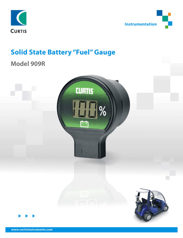
Instrumentation Solid State Battery “Fuel” Gauge Model 909R www.curtisinstruments.com www.curtisinstruments.com 1 Model 909R Solid State Battery “Fuel” Gauge Curtis Model 909R is designed to be used on golf cars and other 36 or 48 VDC battery-powered vehicles to display battery state-of-charge and to charge smart devices. FEATURES ▶▶ Integrated DC/DC converter and USB port allows smart devices to be safely and efficiently charged from the instrument. ▶▶ Battery state-of-charge is calculated using Curtis’ proven algorithm thereby providing an accurate indication of remaining charge following both charge and discharge events. ▶▶ Integrated alarm provides an audible indication of low state-of-charge. ▶▶ Backlit LCD allows easy-to-read operation in low lit environments. ▶▶ Integrated 8-pin AMP connector allows reliable and simple connection to the instrument. ▶▶ The instrument allows for four different discharge/reset battery profiles that are selectable via the connector pins which allows one instrument to satisfy multiple vehicle and/or battery types. ▶▶ 2.5 LCD digits that are 15mm high allow display of state-of-charge from 0 to 100% in large easy-to-read format. ▶▶ Environment protection of IP65 front and rear (with connector installed) ensures operation in harsh environments. ▶▶ USB port includes an attached plug that can be removed while charging and inserted when not charging to environmentally protect the USB port. ▶▶ UL recognition ensure compatibility with global regulatory standards. www.curtisinstruments.com 2 Model 909R Solid State Battery “Fuel” Gauge DIMENSIONS mm Ø60.3 MAX 47.3 MAX 43.5 MAX 24.7 16.6 MAX Ø51.0 16.3 76.0 MAX www.curtisinstruments.com 3 Model 909R Solid State Battery “Fuel” Gauge SPECIFICATIONS Electrical BDI profile selection Four programmable charge/discharge profiles are available and can be selected using external pins PRG1 and PRG2: Operating Voltage Signal Name Min. Nominal Max. B++ (48 V) 36 V 48 V 60 V B+ (36 V) 27 V 36 V 45 V Keyswitch 27 V 36/48 V 60 V Operating Curent 36 V Input 48 V Input Signal Name Typical (mA) Max. (mA) Typical (mA) Max. (mA) B++ (48 V) N/A N/A 17 28 B+ (36 V) 16 28 N/A N/A Keyswitch 375 570 270 425 PRG1 PRG2 Open Open B– B– Open B– Open B– Current The 909R will supply up to 2 A of charging current to the USB charging port at ambient temperatures up to +50°C. At temperatures above +50°C protection circuitry within the 909R will turn off the output current. The figure below depicts the maximum current that the 909R can supply to the USB charging port before the protection circuit is activated at various ambient temperatures. USB Output Current 2 USB Output Current (A) 1.5 1 0.5 Discharge Profile N G G M Discharge Profile Options Volts per Cell Letter Code Full 1.97 2.00 2.04 G M N USB Output Voltage The voltage supplied by USB port is 4.75 V to 5.25 V. Reset Profile B N B N Empty 1.75 1.83 1.73 Reset Profile Options Volts per Cell Letter Code Open Circuit Reset Charge Tracking Reset Full B N 2.090 1.980 2.35 2.230 Charge Tracking Reset Empty 2.10 2.10 Alarm When the BSoC drops below 20 %, the buzzer turns on for 15 seconds, then off for 1 minute. At this point, the threshold for turning the buzzer off becomes 50 %, with no buzzer while charging. Once the battery is charged above 50 %, threshold returns to 20 %. The buzzer is active only when the Keyswitch is active. 60 0 50 –40 –30 –20 –10 0 10 20 30 40 50 60 70 80 90 Ambient Temperature (C) 40 BSoC (%) 30 20 10 0 0 200 400 600 Time (sec) 800 1000 1200 BSoC (%) Alarm ON/OFF www.curtisinstruments.com 4 Model 909R Solid State Battery “Fuel” Gauge SPECIFICATIONS cont’d Environmental Operating Temperature: Gage: –40° C to +85° C. USB Charger: –40° C to +50° C with charge current derated linearly. Storage Temperature: –40° C to +85° C. Humidity: Soak: Designed to meet EN 60068-2-78. Test Cab: Damp Heat, Steady State, 10 days at 93% RH (±3 %), 30° C. Cyclic: Designed to meet EN 60068-2-30. Test Db: Damp Heat, Cyclic (12 hr + 12 hr cycle). Test method variant 1. 6 cycles (each cycle is 24 hrs.), 90 % RH. Ingress Protection: Designed to meet EN 60529 – IP65 front, IP65 rear (with connector installed). Shock: Designed to meet EN 60068-2-27: 3 shocks in all 3 axes in both directions (18 shocks in total), 500 m/s², 11 ms, half sine wave. EMC Specifications Emissions (Broadband & Narrowband) Designed to be in compliance with the requirements of UN ECE/324 Addendum 9 Regulation 10 Revision 4 (6 March 2012) for an Electrical/electronic sub-assembly (ESA) with regard to electromagnetic radiated emissions for the device under test (DUT). Immunity ESD: Designed to meet IEC 61000-4-2: Test level IV (8 kV contact discharge or 15 kV air discharge) according to ISO 10605:2001, Table B.1. Radiated Imunity: Designed to meet: 30 V/m (20 MHz to 1 GHz) when tested per ISO 11452–2, Absorber-Lined Chamber (single sample). Conducted Immunity: Designed to meet IEC 61000-4-4: Test level 4 (4 kV peak, 2.5 kHz repetition rate). Regulatory Approvals UL: UL recognition to UL 583 as authorized in file AU1841 – PENDING. Vibration: General: Designed to meet EN 60068-2-6, Swept Sine Wave method, Section 8.2, 5g, 20 cycles in each plane, 5 to 500 Hz, 1 Octave/min. Amplitude = +/- 15 mm; Amplitude < +/- 15 mm Acceleration = 5g. Random: Designed to meet EN 60068-2-64. Test Fh: vibration, broadband random (digital control) and guidance. Method 1, random excitation, 5 hrs in each axis, 10 to 350 Hz. Resonance: Designed to meet EN 60068-2-6. Vibration sinusoidal. Section 8.1. 5g, 5 mins at resonant points, 1 Octave/min, Swept Sine Wave 10 to 2000 Hz. www.curtisinstruments.com 5 Model 909R Solid State Battery “Fuel” Gauge MODEL ENCODEMENT B = Backlight N = No Backlight Voltage Example Model 909 R 3648 R = 52mm N B = Buzzer N = No Buzzer B Sequential Number O 001 N = Curtis Logo O = No Logo 47.3 MAX CONNECTOR43.5 MAX Ø51.0 16.6 MAX Pin Signal Name Description PIN 1 B– Common PIN 2 B++ High Voltage B+ PIN 3 N.C. — PIN 4 Keyswitch — PIN 5 PRG2 BDI profile select PIN 6 PRG1 BDI profile select PIN 7 B+ Low Voltage B+ PIN 8 USB Return — 4 3 2 1 8 7 6 5 Mating Connector for J1 Part Connector Housing Terminal (18 – 24 AWG) Wire Seal Interface Seal WARRANTY AMP P/N 794821-1 770904-X 794758-1 794772-8 Two year limited warranty from time of delivery. is a trademark of Curtis Instruments, Inc. www.curtisinstruments.com Specifications subject to change without notice ©2016 Curtis Instruments, Inc. 50303 REVA 5/16 6


