Technical Article
MS-2242
.
Reinforced Isolation in
Data Couplers
double insulation approach require galvanically isolated
communications across two layers of insulation without
losing signal integrity. This created the need for devices with
the equivalent electrical strength and reliability of two
redundant insulation systems. This is called a reinforced
insulation device, and it relies on a combination of
construction, type testing and continuous monitoring in
production to ensure safety equivalence to two independent
systems.
Mark Cantrell, Applications Engineer,
Analog Devices, Inc.
IDEA IN BRIEF
Reinforced insulation in data isolators is designed and
qualified to provide the protection of double insulation
We will examine how reinforced insulation is achieved
in optocouplers and digital isolators with respect to
construction and test requirements under IEC 60950 and
the related IEC 60747-5-5 and VDE-0884-10 standards, as
well as differences with other accepted IEC standards for
both types of isolators.
systems while providing the data transmission performance
available with a single isolation barrier.
T
he primary tenet of electric shock safety is that there
must be the equivalent of two independent
insulation systems between dangerously energized
circuits and any conductor that can be accessed by the user
of an electrical device. One of these insulation systems could
be a safety grounded enclosure paired with a single layer of
internal insulation. Another approach is to use two
insulation systems arranged to provide redundant
protection. As a result, complex electrical systems using the
Safety Isolation
Isolation is required in modern systems for many reasons:
communication to high side components in battery charging
systems or motor drives, breaking ground loops in
communications systems, or protecting users from
dangerous line or secondary voltages. The level of isolation
is determined by the level of safety required for the specific
application. Functional isolation provides no protection to a
user, only the insulation required for the component to
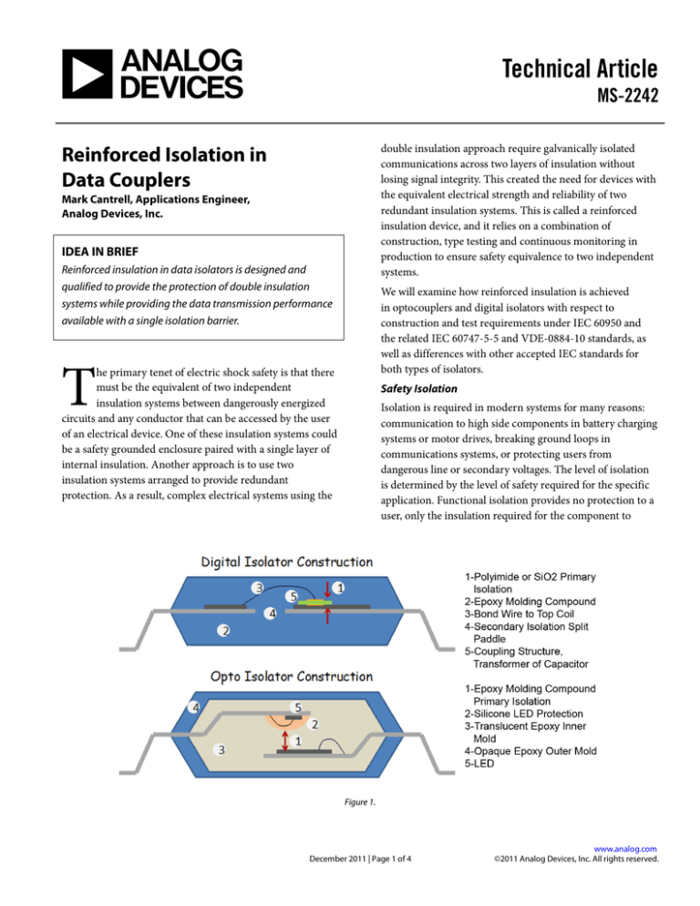
Figure 1.
December 2011 | Page 1 of 4
www.analog.com
©2011 Analog Devices, Inc. All rights reserved.
MS-2242
Technical Article
layers of isolation. The impracticality of doubling up data
isolation devices created the need for single components that
directly connect across a double insulation boundary
without sacrificing safety. This type of component (Figure 1)
is classified as having reinforced insulation.
function properly. Basic insulation provides a level of
insulation from shock that is adequate for protection of an
operator if the insulation is fully intact. However, to protect
people from hazardous voltages, regulations require that two
independent insulation systems be present: basic insulation
for shock protection, and a supplemental layer so that if a
fault breaches one insulation system, a redundant system
will still provide safety to the operator. This type of
arrangement is called double insulation. When evaluating
insulation systems, the primary requirement is safety, not
electrical functionality, so the failure criterion during
evaluation is whether the isolation barrier is intact after the
qualification—if the part still functions to the original
specifications, it is an added bonus.
Component Level Requirements
Component reinforced insulation is evaluated in two ways:
external dimensions of the component such as creepage,
clearance, and tracking index; and internal electrical
performance. Internal and external requirements are
handled in very different ways.
Creepage is the shortest distance along the surface of a
component between electrically isolated conductive
structures, such as component pins. Clearance is the
shortest distance between isolated conductive structures in a
component, but it is not constrained to be on the surface, so
the path can jump over grooves and be suspended over
ridges. In simple geometries, the creepage and clearance
path are often the same. The illustration shows the creepage
path for a JEDEC standard SOIC since this style of packge is
used for many isolation devices. For this style of package, the
creepage and clearance have the same path and length.
Creepage is always greater than or equal to the clearance. An
additional external property of components that is critical to
insulation ratings is the Comparative Tracking Index (CTI).
This is a measure of how easily an insulating material will
erode under electrical discharge. Higher tracking voltages
will allow smaller creepage while still maintaining safety.
An example of a reinforced insulation system is the feedback
control loop in a power supply. Information about the
current output voltage level must flow from the SELV (safety
extra low voltage) side of the ac-to-dc converter to the line
side of the power supply. Operators can be in contact with
the SELV side of the power supply, so two independent
isolation systems or a reinforced insulation system must be
present in the data paths to protect operators from shock.
Passive components like resistors or capacitors can be run in
series without significant functional degradation, but putting
two data isolators into the path would be impractical for
several reasons. First, analog data would lose fidelity, and
digital data would have long propagation delays and added
jitter. Secondly, it would create the need for an intermediate
power supply to run the coupler interfaces between the two
Figure 2.
www.analog.com
©2011 Analog Devices, Inc. All rights reserved.
December 2011 | Page 2 of 4
Technical Article
MS-2242
External dimensions must be equivalent to the total
distances provided by basic and supplemental layers of a
double insulation system. In general, all creepage and
clearance requirements are twice as large for reinforced
components as for basic/supplemental rated components.
An example is shown in Figure 2 of two common operating
conditions and the creepage and clearances required. This
approach is taken since the external environment and
surface properties determines the external spacing
requirements. These include the amount of contaminants
expected, the air pressure, and the tendency of the outer
surface of a component to be eroded by surface discharges,
called tracking.
For internal properties of components, the quality of the
insulation is more important than having a specific quantity
or thickness of insulation. The manufacturer can
demonstrate that the part has the required electrical
properties to withstand the voltage stresses both long and
short term.
The requirements of the IEC 60950 standard are for office
and telecom equipment and to a large extent for medical
devices. The external dimensions and materials are readily
verified with a micrometer and some bulk material testing
for tracking index. For internal requirements, there are three
approaches for qualifying the component.
•
•
•
The component can be evaluated as if it contained
only solid insulation. This is the simplest approach
since it requires that all of the internal distances
through the insulation or along cemented joints are
greater than 0.4mm. No further type testing is
required. However, it is difficult to make a high
performance data coupler that meets these
requirements. It is widely believed that the 0.4 mm
minimum insulation thickness applies to all
reinforced isolation devices; this is not the case and
is a point of confusion for many engineers.
If the component is an optocoupler, then the IEC
60747-5-5 standard must be applied. This is a
rigorous standard specifically designed to qualify
optocouplers for reinforced insulation and has a
battery of type tests and life tests with isolation
withstand verification tests after each one.
The component can be treated as a semiconductor
device. This category of devices has a set of type
tests similar to the IEC 60747-5-5 requirements.
This approach is used by digital isolators since the
testing requirements of the optocoupler standard
are specifically tailored to optocoupler structures.
Qualification to and maintenance of a reinforced rating is
accomplished in three phases.
1.
Materials and dimensions are evaluated, and
electrical type testing is conducted. Testing includes
thermal cycling, limited life testing, and electrical
overstress that would cause heating or catastrophic
insulation failure. The integrity of the isolation is
checked with a voltage withstand test after each
environment or test. IEC 60747 type testing is
summarized in Table 1.
Table 1. Type Tests
Materials
CTI
Flammability
2.
3.
Electrical
Withstand
Partial Discharge
Insulation Resistance
Surge
Overload
Mechanical
Thermal Cycle
Thermal Shock
Vibration
High Temp Storage
Creepage/Clearance
After the part has been approved based on its
dimensions and type testing, insulation integrity is
checked for each device as it is manufactured by a
voltage withstand test. In the case of IEC 60747-5-5
or equivalent certifications, a partial discharge
insulation quality test is also performed on each
device.
Periodic audits are conducted by the certifying
body to verify material sets and dimensions have
not changed and that all assembly line tests are
being properly conducted with calibrated
equipment. Some of the type tests periodically
repeated on a sample basis and reviewed by the
auditor.
Trends in Isolation Requirements
The previous discussion centered around one of the most
widely applied standards. Different standards can have
disparate requirements at the component level. It even varies
from edition to edition within a single standard. This is
becoming less problematic as IEC is trending toward a
unified approach. This will likely take a significant amount
of time to achieve since the individual standards committees
still have significant independence. A unifying trend in
application of system level standards is the availability
component level standard, such as IEC 60747-5-5. If such a
standard exists for a component, it can be applied instead of
December 2011 | Page 3 of 4
www.analog.com
©2011 Analog Devices, Inc. All rights reserved.
MS-2242
Technical Article
the particular requirements of a system level standard.
Currently this standard only applies to optocouplers, not
other newer digital isolators; however VDE has created a
draft standard VDE0884-10 which applies the insulation
tests of the IEC 60747-5-5 standard to digital isolators.
Both standards set a high bar for reinforced insulation
including surge testing at levels of 10 kV or higher. Very thin
insulation layers will not pass this test, and it has proven to
be the discriminating test for many optocouplers and digital
isolators for qualification as reinforced insulation.
Components that cannot meet the requirements usually fall
back to the IEC 60747-5-2 standard which can be applied to
basic insulation. This is yet another confusing point for
designers of isolated systems where it is assumed that an IEC
60747-5 qualification automatically confers reinforced
status. The IEC committees are currently working to revise
the IEC 60747-5-5 standard to include digital isolators. The
next unified standard will be applicable across all IEC system
level standards and should help to eliminate confusion in the
future.
Conclusion
Reinforced insulation in data isolators is designed and
qualified to provide the protection of double insulation
systems while providing the data transmission performance
available with a single isolation barrier. Externally, the
components have a creepage and clearance requirement that
is equivalent to twice the basic insulation requirement.
Internally, insulation either meets the requirements of solid
insulation including through the insulation minimum
distance, or it receives extensive type testing and assembly
line testing during production. The availability of a
reinforced insulation rating which is verified by test rather
than detailed structural requirements allows innovation in
insulation technology to be qualified without rewriting the
standards for each new technology.
RESOURCES
For information and resources on isolation products, visit
www.analog.com/iCoupler.
Share this article on
Follow us on Twitter: www.twitter.com/ADI_News
ABOUT THE AUTHOR
Mark Cantrell is an applications
engineer for the digital isolation group
at Analog Devices, Inc. (ADI). Prior to
joining ADI, Mark spent six years at
California Eastern Laboratories, where
he was responsible for applications
support for NEC’s optocoupler and
solid-state-relay product lines. Mark’s experience also
includes 17 years at Lockheed Martin Missiles and Space,
where his job as a radiation-effects test engineer included
work on the Gravity Probe B satellite program. Mark
received his MS in physics from Indiana University. He can
be reached via email at mark.cantrell@analog.com.
One Technology Way • P.O. Box 9106 • Norwood, MA 02062-9106, U.S.A.
Tel: 781.329.4700 • Fax: 781.461.3113 • www.analog.com
Trademarks and registered trademarks are the property of their
respective owners.
TA10396-0-12/11
www.analog.com
©2011 Analog Devices, Inc. All rights reserved.
December 2011 | Page 4 of 4


