Abridged Datasheet
LX5563
2.4 - 2.5 GHz LNA With Bypass
Description
Features
The LX5563 is a low noise amplifier (LNA) for WLAN
applications in the 2.412 to 2.472 GHz frequency
range. It operates with a single voltage supply of 3.3V,
and features both high gain and bypass modes.
2.412GHz to 2.472GHz frequency range
Single 3.3V operation
14dB gain in high gain mode; 7dB loss in
bypass mode
1.3dB noise figure
Input IP3 = +7.5 dBm (high gain)
Input P1dB = -3 dBm (high gain) or +18dBm
(bypass)
Single control enables LNA in high gain mode,
or places LNA into bypass mode.
The LNA is fully matched on both the input and output
ports; no external inductors or matching is required. It
includes all bias circuitry and operates with a digital
control signal. Only one external bypass capacitor on
the supply line is required.
The LNA is packaged in a 1.5x1.5x0.5 mm dual-flat
no-leads (DFN) package.
Applications
2.4GHz Wi-Fi RF front ends
802.11 b/g/n/ac radios
Laptops, Tablets
Smartphones
Wireless Access Points
Routers
Block Diagram
VCC
RFIN
LNA
RFOUT
LNAEn
LX5563
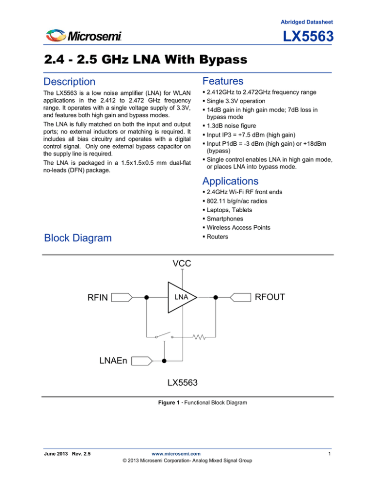
Figure 1 · Functional Block Diagram
June 2013 Rev. 2.5
www.microsemi.com
© 2013 Microsemi Corporation- Analog Mixed Signal Group
1
2.4-2.5 GHZ Low Noise Amplifier With Bypass
Pin Configuration
1
RFIN
2
GND
3
XX
3
LNAEn
6
VCC
5
RFOUT
4
GND
Figure 2 · Pinout
Top view XX = Encoded date code
1.5 x 1.5 x 0.5mm DFN package
Ordering Information
Ambient
Temperature
0°C to 70°C
Type
Package
Part Number
Packaging Type
RoHS2 compliant,
DFN 1.5x1.5 6L
LX5563LL
Bulk / Tube
LX5563LL -TR
Tape and Reel
Pb-free
Pin Description
Pin Number
2
Pin Designator
Description
1
LNAEn
LNA Enable/Bypass mode select
2
RFIN
RF input. This pin is AC coupled to the transistor; no DC blocking is required.
3
GND
Ground
4
GND
Ground
5
RFOUT
6
VCC
RF output. This pin is AC coupled to the transistor; no DC blocking is required.
3.3V Supply voltage
Absolute Maximum Ratings
Absolute Maximum Ratings
Value
Parameter
DC Supply Voltage, RF off
4
V
+10
dBm
0 to 70
°C
-65 to 150
°C
RF input power
Operational ground slug temperature
Storage temperature range
Units
Note: Stresses in excess of these absolute ratings may cause permanent damage. The device is not
implied to be functional under these conditions.
General Electrical Characteristics
Symbol
Parameter
Test Condition
Min
Typ
Max
Units
VCC
Operating voltage
3
3.3
3.6
V
VIH
Logic high
LNAEn
VIL
Logic low
LNAEn
VCC-1.1
3.6
V
0
0.8
V
ESD
All pins, HBM
1500
V
Note: The device may be operated safely over these conditions. However, performance is guaranteed only
over the conditions defined in the electrical specifications. Although this device is designed to be as
robust as possible, Electrostatic Discharge (ESD) can damage this device. This device must be
protected at all times from ESD. Static charges may easily produce potentials of several kilovolts on
the human body or equipment, which can discharge without detection. Industry-standard ESD
precautions should be used at all times.
Application Information
The LX5563 is fully matched on both RF ports. No external matching is required. An external decoupling
capacitor is recommended on the supply line, as shown in Figure 4 · .
C1 = 1 µF
Vcc
LNAen
RFin
GND
LNA
LNA
RFout
GND
Figure 3 · Application Schematic
Figure 4 · Application Schematic
3
2.4-2.5 GHZ Low Noise Amplifier With Bypass
Package Outline Dimensions
The package is halogen free and meets RoHS2 and REACH standards.
D
Pin 1 ID
D2
L
E2
E
A3
b
e
A
A1
DIM
A
A1
A3
b
D
D2
E
E2
e
K
L
MILLIMETERS
INCHES
MIN
MAX
0.41
0.50
0.0
0.05
0.15 REF
0.18
0.30
1.50 BSC
1.05
1.30
1.50 BSC
0.55
0.80
0.50 BSC
0.15
0.125
0.225
MIN
MAX
0.016
0.020
0.0
0.002
0.006 REF
0.07
0.012
0.059 BSC
0.041
0.051
0.059 BSC
0.022
0.031
0.20 BSC
0.006
0.005
0.009
K
Figure 5 · 6 Pin DFN Package Dimensions
4
Recommended PCB Footprint
Recommended PCB Footprint
6X 0.55
6X 0.35
0.15 x 45°
6X 0.25
0.60
0.50 Pitch
0.762
1.20
7X Exposed Solder Area
0.20
0.05
R 0.254 2X Thermal Vias
0.35
0.70
Figure 6 · PCB Layout Footprint (Top View)
PRODUCTION DATA – Information contained in this document is proprietary to Microsemi and is current
as of publication date. This document may not be modified in any way without the express written
consent of Microsemi. Product processing does not necessarily include testing of all parameters.
Microsemi reserves the right to change the configuration and performance of the product and to
discontinue product at any time.
5
Microsemi Corporation (NASDAQ: MSCC) offers a comprehensive portfolio of semiconductor
solutions for: aerospace, defense and security; enterprise and communications; and industrial
and alternative energy markets. Products include high-performance, high-reliability analog and
RF devices, mixed signal and RF integrated circuits, customizable SoCs, FPGAs, and
complete subsystems. Microsemi is headquartered in Aliso Viejo, Calif. Learn more at
www.microsemi.com.
Microsemi Corporate Headquarters
One Enterprise, Aliso Viejo CA 92656 USA
Within the USA: +1(949) 380-6100
Sales: +1 (949) 380-6136
Fax: +1 (949) 215-4996
© 2013 Microsemi Corporation. All rights reserved. Microsemi and the Microsemi logo are trademarks of
Microsemi Corporation. All other trademarks and service marks are the property of their respective owners.
LX5563.0/0.2.5

