Technical Datasheet

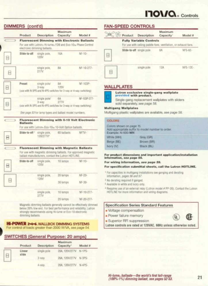
DIMMERS (cor.t
Product ll FlUOreaeent Otmmlnq w i t h El
Foi use 'jvftfl Llitron. Hi Iur4* F3B anc t toctTOTic aimmlng MlMts llMt-M-ell t«gli KM.
1MW
16A single pott.
Z77V
nov/Q
« Controls
FAN-SPEED CONTROLS v Product Description Capacity fully Variabto Control*
For UM wttti ceiling prtflu tana, venklaton. ci n
IIMIH-M angle POM M sngla POM NFS12S-
•tlM MigltPOli/ V HF IMP
3w» 120V
[tax »f» MRS M IMPS nridles » J-«a» or 4-vw, urfeMng)
Z77V
IIM Mil MfS M IMPS MUM »X 3-«W or 4-n, MKDr«:, ta? Olpf tt tor feme lyvtl 1M tMtt IHM* Write >
Fluo»»»««iit Oknmln* wtth O.10 VoU ll.clron.c
fw use wftn Lulron. tcp-tCU 10-WI Option Dlitotls
SIlMtogfl ungHpM. MWttra NFT
12O777V
Fluorottcont Dimming with M««n*tic B«tla*ts far use with magnetic (Urnmrng ballasts FM ipcrowd magnetK naiiin iMnuaaiinn. Mrtaa «»imron HOTIIHE jlngie pen.
IMV
20 lamps
30 lamps
IKMO-
W-30-
WALLPLATES
Lutron w i t l u s i v e iin.iln <j*nq *allpl,il.
provlcl^rl with product.
Smgl.-9«i9 reptocenwrt vmpMes with ««o.r» sold MpnMyt see P«B« S8
«*e>M0i Set
COLORS
Colors shown on page T5.
Add acpropniks suffn to modal numb* to order.
tgampku N-eOO-WH
Gny(GR|
NorylrV) Btack «4
For product dtm*n»ioni and Important applicaHonrlnatattatian
Inforrnatktn. »•• p«o» 5S.
For wiring Imfomvatiorv •*• pa*o 3V.
For »e«cHkc«tki«> vubmrnal fthooU. call the Urtron hX/TUMC.
mlorm i
' • * > * • " day (Huron model IPP-20). Contact I
•onmdat
Magmilc HmmUg MUa gsmnlly omul M iincuvcsry dlmmtd bmw 20* tw mo Fw bnt penormiiici KM mMUtr. Litrw
Speclflcatton Sajries Standard Features
a Voltage compensation
a Panel lalure memory rtTN rfjf.
a Superior RFI suppression ^^
LiHiw cealrolt in rated n 1JOVAC MHz mini otherwise noled
Ht-POWER 2-** WALLBOX OMMJNG SYSTEMS f or control ot loads greater man 2000 W/VA. Mepage 54
I
SWITCHES (General Putpoao: 20 amps)
Maximum
Oo»crvit>on Capacity Model • bnglt ( JOA, 120V.7.'™ N-IPS-
3 way JOA.1JOV/277V N-3PS
20A.120V/^7V IMPS-
Htlumt. tultlOs— Hie *orH"l Hal
(IOBV TV Hanrmas bOUtt. M*
WALLBOX TECHNICAL & INSTALLATION INFORMATION
WALLBOX AppucATioN/lNSTAUjvnoN NOTES & DIMENSIONS
Number of dimmers per lighting circuit
Use only one Lutron« dimmer per lighting circuit. Do not use two or more Lutron dimmers or base units in a 3-way circuit.
Multi-phase applications
In multi-phase applications, use a separate neutral for each phase containing a dimming circuit. For additional information, call the Lutron HOTUNE and ask for Application
Note #17, "Common Neutral Interaction" (P/N 360-283).
Dimming low-voltage lighting
A. Do not use electronic low-voltage or standard incandescent dimmers with magnetic low-voltage transformers. For additional information, call the Lutron
HOTLINE and ask for Application Note #19, "Guide to
Dimming Low-Voltage Lighting" (P/N 362-219).
B. Operation of a dimmed magnetic low-voltage circuit with all lamps inoperative or removed may result in current flow in excess of normal levels. To avoid possible transformer overheating and possible premature transformer failure, Lutron strongly recommends the following:
1. Do not operate dimmed low-voltage circuits without operative lamps in place; and
2. Replace burned-out lamps as quickly as possible; and
3. Either use transformers which incorporate thermal protection or fuse transformer primary windings.
Lamp buzz
Due to various configurations of incandescent lamp filaments and lamps, some lamp types may buzz when dimmed, To decrease the noise, you may use smaller wattage lamps, physically smaller lamps, Rough Service
(RS) lamps or low noise lamps. If these solutions are not viable or do not yield acceptable results, lamp debuzzing coils (LDCs) are recommended.
For additional information, call the Lutron HOTLINE and ask for Application Note #3, "Lamp Buzz with Solid-State
Incandescent Dimmers" (P/N 360-476).
VAREO and NOVA T* PRODUCTS tfova T * products shown
Front Front
Small Control Large Control
(Nova T 1 only)
B
(114 mm)
B
Proflle u .30"
11 (7.5 mm) ft—
4.5" IP) T2.7S"
[114mm} f l l I (70m m)
2.75"
{70 mm
NOVA, CENTURION and ATHENA PRODUCTS
Nova products shown
B
SPACER, LUMEA 2, MAESTRO, DIVA, and
SKYLARK PRODUCTS
Maestro product shown (with Claro wallptate)
Front Profile
I—I 'some models
1 - 3 1 " ' up to 1.44"
(33 mm) (37 mm)
GLYDER and ROTARY PRODUCTS
Rotary products shown some models up to 1.71"
43.4 mm)
The following LDCs are available from Lutron:
Model # Rated Capacity
LDC-10-TCP 600-12QOW
LDC-16-TCP 1201-1920W
Dioded Lamps
Sylvania Capsylite. and Philips Masterline „ lamps can cause operational malfunctions with solid-state electronic equipment. For additional information, call the Lutron
HOTLINE and ask for Application Note #23, "Dimming
Sylvania Incandescent Capsylite Lamps" (P/N 360-477).
| Fan motor hum
Fully variable fan-speed controls may cause some fan motors to hum. The use of a "quiet" fan-speed control is recommended for each ceiling paddle fan.
High-end output
Dimmers, including GRAFlK Eye, and Hi-Power 2»4«6 modules, do not produce the same high-end light output as a switch. Some loss of high-end output will be experienced, though usually not noticeable in everyday use.
Dimmer Mounting
All dimmers must be mounted vertically.
ARIADNI PRODUCTS
H sv
124 mml
Specify Lutron's exclusive 3-lamp dimming ballast, see pages 52-53
55
WALLBOX TECHNICAL & INSTALLATION INFORMATION
PRODUCT WIRING DIAGRAMS
AY1V-600P-.................... 1
AYLV-603P-.................. 78
Athena,.
T-600..............................1
T-1000.............................1
T-1500.............................1
T-2000............................ 1
Centurion*
C-10P-............................1
C-103P-........................7.8
C-600-............................1
C-600P-......................... 1
C-603P-.......................7.8
C-1000-.......................... 1
C-1500-.......................... 1
C-2000-..........................1
Diva.
DV-1PS-...........................1
DV-3PS-........................78
DV-4 PS-..........................8
DV-10P-.......................... 1
DV-103P.......................78
DV-600P-........................1
DV-603P-.....................7,8
DVELV-300P-...................3
DVELV-303P-...................9
DVF-103P-.................... 27
DVF-103P-277-............. 27
DVFSQ-F-.................. 2,78
DVLV-10P-.......................1
DVLV-103P-.................. 7.8
DVLV-600P-.................... 1
DVLV-603P-................. 7.8
Gtyder.
GFS-5E-.........................4
GL-10P-..........................1
GL-103P-..................... 7,8
GL-600-......................... 1
GL-600P-.......................1
GL-603P-.....................78
GL-1000-........................ 1
G1V-600-........................ 1
To find the appropriate wiring diagram tor any Lutron wallbox product, find the product model number and the corresponding wiring diagram number in the table below. Wiring diagrams can be found on pages 60-67. Installation instructions supplied with each product must be read prior to actual product installation.
Product Product Wiring
Diagram
Number
Wiring
Diagram
Number
Ariadni.
AY-10P-...........................1
AY-10PNL-......................1
AY-103P-...................... 78
AY-103PNL-.................. 7,8
AY-600P-........................1
AY-600PNL-................... 1
AY-603P-..................... 7,8
AY-603PNL-................. 7,8
AY2-LFSQ-................... 13
AYF-103P-.................... 27
AYF-103P-277-.............. 27
GRAFIK Eye.
GRX-2104..................... 21
GRX-2502 .................. ..22
GRX-2503 .................... 22
GRX-2504 ...... .............. 22
GF1X-27S2..................... 22
GRX-2753 .................... 22
GRX-2754 .................... 22
Hi-Power 2'4'6.
HP-2 ........................ ....20
HP-4............................ 20
HP-6 ............................ 20
Lumea 2.
LT-1PSH- ........................ 1
LT-3PSH- ..................... 7,8
LT-4PSH- ....................... 8
LT-103PH-.................. 2,7,8
LT-600H...... ................ ....1
LT-603PH...... ............ 2,7,8
LT-CJH-. ...................... .15
LT-PJH-. ....................... 16
LTH-V-303PH- ................ 9
LTPSQ-2H- ..................... 1
LJFSQ-FH-...... ........... .....1
LTLV-603PH...... ......... 2,7,8
LTR-15-GFCIH- ............. 10
LTB-15H- ....................... 17
Maestro*
MA-R-. ....................... ...18
MA-600- ................... 12,18
MA-1000- .................. 12,18
MA1V-600- ................ 12,18
MALV-1000-. .............. 12,18
Nova«
N-1PS-.......
N-3PS- ......
N-4PS-.......
N-600-........
........ 1
...... 7,8
N-1000- .......................... 1
U-1003P-.... .............. .2,7.8
N-1500- .......................... 1
N-2000-..........................1
N-2003P- ...................2,78
NEUM50- ...................... 3
NF-10- .......................... 26
NF-10-277-.................... 26
NF-103P-.......................27
NF-103P-277-.. ............ ...27
NF-20-..........................26
NF-20-277-................... 26
NF-30- ......................... 26
NFS-6E- ......................... 4
NFS-12E-........................4
NFTV- ..............................'
Wiring
Diagram
Number
- ........................ 3
NLV-603P-................. 2,78
N1V-1000- ........ ............... 3
NLV-1003P-... ............. 2,7,8
NLV-1500-....................... 3
NLV-1503P-................ 2,7,8
NW-SD03P- ............... £7,8
NovaT*.
NT-1PS-.......................... 1
NT-3PS-.......................7.8
NT-4PS- .................... 8
NT-600-... ................ .......1
NT-BOO-IR- ..................... 3
NT-1000....... .............. .....1
NT-1000-IR-.................... 3
NT-1003P- ..................2,7,8
NT-1500-.........................1
NT-CJ-..........................15
NT-PJ-..........................16
NTA-2- ........................... 6
NTB-600-....................... 6
NTB-1000-.... .................. 6
NTEUA300- .................... 3
NTF-10-... ..................... 26
NTF-10-277-.................. 26
NTF-103P-.....................27
NTF-103P-277 .............. 27
NTFS-6E- ....................... 4
NTFS-12E-......................4
NTFSQ- .......................... 1
NTLV-600- ...................... 1
NTLV-603P-.... ........... 2.7,8
NTLV-1000- ..................... 1
NTLV-1003P-.............. 2,7.8
MTLV-1500-.......... ........... 1
NTLV-1503P-... ........... 2,78
NTR-15-.. ....................... 17
NTR-15-GFCI-............... 10
NTR-20-........................ 17
NTR-20-GFCI-.............. 10
Rotary
D-600P-......................... 1
D-600R- ......................... 1
D-603P-.......................7.8
DNG-600P-IV................. 1
DNG-603P-IV .............. 78
FD-12-W ....................... 25
FS-5E-IV.........................4
FS-5F-............................1
FSQ-2F-......................... 1
LUTRON electronic fluorescent dimming ballasts— c
0
20 years of unmatched quality, see pages 52-53.
3a
Wiring
Diagram
Number
Skylark,
S-10P-............................ 1
S-10PNL-........................1
S-103P-........................78
S-103PNL-................... 7,8
S-600-............................1
S-600P-......................... 1
S-600PNL-..................... 1
S-603P-....................... 7,8
S-603PNL- .................. 7,8
S-1000-...........................1
S2-L-............................. 5
S2-LF-.......................... 13
S2-LFSQ-..................... 13
SELV-300P-.................... 3
SELV-303P-.................... 9
SF-10P-........................ 26
SF-103P-...................... 27
SF-12P-277-.................. 26
SF-12P-277-3-.............. 27
SFS-5E-......................... 4
SFSQ-F-......................... 1
SFSQ-LF-....................... 4
SIV-600P-...................... 1
S1V-603P-.................... 7,8
Spacer*
AD-............................... 18
SP-600-......................... 1
SP-600M-................. 12,18
Vareo.
V-600-....................... 12,18
V-1000-......................12,18
VETN-1000-...............14,19
VETS-R-....................... 18
VETS-1000................ 12,18
VETS-1000-SL-......... 11,14
VETS-A-SL-.................. 11
VF-10-.......................23,24
"Requires use of an external relay (Lutron model tt PP-20).
Contact Lutron HOTLINE for more information and wiring diagrams.
WALLBOX TECHNICAL & INSTALLATION INFORMATION
PRODUCT WIRING DIAGRAMS
Wiring Diagram #12
DUnmwC
6QH2
Neutral
Wiring Diagram *2
CoriBoI
Wiring Diagram #3 r I
Wiring Diagram #4
Fan-Sp&sd
Wiring Diagram #5
Wiring Diagram #6
Note: Only one dimmer can be used per 3-way circuit. Follow this diagram when Incorporating a 3-way on/off switch witti the dimmer.
The 3-way switch must be wired on line side of me dimmer.
Wiring Diagram #10
Wiring Diagram #16 iWtirlo.l
1 2 0 .
GOHi
Wiring Diagram #11 feadlwy AuiHay
Tepswirch Tapswte,
Wiring Diagram #17
Rflceplaste
Blac«
I I l"l
While
^KS
SO,™
60 To Order—Call LUTFION Customer Service 610-2823800

