OLIMEX© 2012
PIC-IO User's Manual
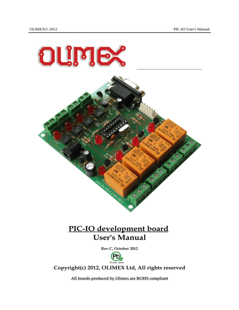
PIC-IO development board
User's Manual
Rev.C, October 2012
Copyright(c) 2012, OLIMEX Ltd, All rights reserved
All boards produced by Olimex are ROHS compliant
OLIMEX© 2012
PIC-IO User's Manual
INTRODUCTION:
PIC-IO board was designed as simple platform which to allow control of appliances and
devices with PIC, the idea was to build something like tiny PLC controller which is possible
to program in C or assembler instead of the weird PLC relay language.
Let’s see what we have on board:
Four High voltage/ High Current relays – with NO-NC-COM contacts available on terminal
block. The relay switching current is rated: 15A/125VAC, 10A/250VAC, 15A/24VDC. Note
that these relays are good for switching resistive loads, but if you have to commutate
inductive loads the relays will wear off quickly due to the sparking when disconnect the
inductive loads (like motors).
Each relay have status LED associated with it so you can easy see which relay is in ON and
which in OFF state.
O1 is connected to RA3 CMP1 and PIC CCP module can be used to generate ON/OFF pulses.
O2-O3-O4 are connected to RA2-RA1-RA0.
Four opto-isolated inputs will allow to detect voltages in range +5-24VDC. Opto-couplers are
fast and switch On/Off for 10 uS, so quick signals could be detected.
!NOTE for owners of MOD-IO prior to revision C1: the above information is correct
only for the opto-isolated couplers – the board is capable to handle up to 22VDC for
them. You need to swap R1, R2, R3, R4 - 330R resistors with 470R ones be able to use
24VDC! This has been fixed in the latest revision as seen in the schematics.
I1 is connected to RA4 and is good for counting as this pin is connected to PIC T0CKI.
I2 is connected to RB0 which is INT and generates interrupts.
I3 is connected to CCP1 and is good for pulse width measurement.
I4 is connected to RB4.
The inputs have status LEDs so easy could be seen which input have voltage. Note that the
optocouplers inverse the levels i.e. when on the input have +5V the PIC pin will read “0” and
vice versa.
Status LED is connected to RB5.
PIC-IO have RS232 connector, but the driver is made by tricky level shifter which uses the
other side RS232 negative levels to generate the PIC-IO levels, so on the other side you must
OLIMEX© 2012
PIC-IO User's Manual
have real RS232 driver (like PC) if you try to connect two PIC-IO boards by RS232 the
connection will fail as no one of the boards will generate the negative levels.
The on-board ICSP connector allow you to program the PIC on the board without pulling it of
the socket, by ICSP programmer like PIC-MCP, PIC-MCP-USB, PIC-PG1, PIC-PG2, PICPG3, PIC-PG4 or to program and debug it with PIC-ICD2, PIC-ICD2-POCKET or PICICD2-TINY. IMPORTANT: all programmers provide power supply through ICSP connector
during the programming PIC-IO should not be powered via the external power jack!
The power supply circuit have protection diode for reverse connection. The positive point is
the internal pin of the power jack. The input voltage could be in range 12–14V DC.
The oscillator circuit is made with 20 Mhz crystal oscillator, so you can run your PIC at
maximum performance.
The RESET is connected with 10K to +5V and allow safe use of PIC-ICD2 or PIC-MCP
programming.
OLIMEX© 2012
PIC-IO User's Manual
FEATURES:
•
•
•
•
•
•
•
•
•
•
•
ICSP/ICD connector for programming and debugging
RS232 interface
DIL18 socket
Quartz crystal 20Mhz
LED to RB5 through jumper
Four opto-isolated inputs with status LEDs
Four Relays 10A/250VAC with status LEDs
Power plug-in jack, accept AC and DC input
Four mounting holes 3,3 mm (0,13")
FR-4, 1.5 mm (0,062"), green soldermask, white silkscreen component print
Dimensions 100x80 mm (3,9x3,15")
OLIMEX© 2012
PIC-IO User's Manual
HARDWARE:
+12V
PWR+
IN
-2
-1
C1
1N4004
+12VDC
6
5
2
4
R19
470K
R2
IN2-2
LED2
1
6
5
D2
1N4148
2
4
R20
470K
4N37
R3
IN3-1
IN3-2
LED3
6
5
2
4
R21
470K
4N37
R4
IN4-1
IN4-2
LED4
10K
C4
20p
C5
20p
+5V
16
Q1
20MHz
R9
15
RESET
4
10K
VDD
6
5
2
4
5
R26
I4
R22
470K
4N37
10K
GND
RB7/T1OSI
RB6/T1CKI
RB5
RB4/PGM
RB3/CCP1
RB2/TX/CK
RB1/RX/DT
RB0/INT
RA7/OSC1
RA6/OSC2
RA5/MCLR
RA4/T0CKI/CMP2
RA3/AN3/CMP1
RA2/AN2/VREF
RA1/AN1
RA0/AN0
OK4
1
470
D4
1N4148
U1
14
C7
100n
R25
I3
GND
+5V
10K
OK3
1
470
D3
1N4148
RESET
+5V
R24
I2
R5
T1
2N3904
2K
OUT1-2
OUT1-1
10K
OK2
470
OUT1-3
REL1
O1
100uF/16VDC
GND
R23
I1
4N37
IN2-1
100n
R27
1
220uF/25VDC
C3
VSS
PICICSP
+12V
1
2
3
4
5
6
REL2
H200
D7
1N4004
R16
1.5K
ICSP
13
12
11
10
9
8
7
6
I4
I3
T XD
RXD
I2
3
2
1
18
17
I1
O1
O2
O3
O4
R14
PIC_18pin
OUT2-3
REL2
O2
330
R6
T2
2N3904
2K
LED9
OUT2-2
OUT2-1
GND
+12V
REL3
H200
D8
1N4004
+5V
LED6
10K
IN1-2
LED1
D1
1N4148
C2
LED5
R15
1.5K
OUT
GND
+5V
OK1
470
D6
1N4004
R28
R1
IN1-1
+5V
10K
D5
REL1
H200
VR
78L05
+12V
LED7
R17
1.5K
+5V
OUT3-3
REL3
RXD
R11
4,7K
GND
D10
R12
1N4148
10K
C6
10uF/25VDC
+
1
2
3
4
5
GND
T3
2N3904
2K
R13
10K
10K
R7
OUT3-1
T6
2N3904
+12V
D11
1N4148
GND
OUT3-2
10K
RS232
6
7
8
9
O3
T XD
R29
R10
T5
PNP2N3906
REL4
H200
D9
1N4004
LED8
R18
1.5K
OUT4-3
REL4
Copyright (C) 2002, OLIMEX Ltd
http://www.olimex.com/dev
T4
2N3904
2K
OUT4-2
10K
PIC-IO_rev_C1
R8
R30
O4
OUT4-1
OLIMEX© 2012
PIC-IO User's Manual
SOFTWARE:
DEMO1:
PIC16F628-I/P
CONTROL SOFTWARE
This is demo code, which allow control of the PIC-IO inputs/outputs via PC
with Hyper terminal.
Connect PIC-IO RS232 with cable to your PC and run Hyper terminal with
these settings: 9600,8,N,1,NONE. When you apply power this will be seen
on the Hyper terminal window:
***************************
* PIC-IO CONTROL
*
* (C) 2007, OLIMEX Ltd*
***************************
>_
To read the inputs in binary format type “r”, PIC-IO will respond with
something like:
%0000
if all inputs are 0 or
%1111
if all inputs are 1 (i.e. +5V is applied)
the inputs are with right less significant bit i.e. the order is: I4 I3 I2 I1
To read the inputs in HEX format type “R”, PIC-IO will respond with
something like:
$0
if all inputs are 0 or
$F
if all inputs are 1
To change the outputs type “w0101”, this will switch on relay 1 and relay 3
and will switch off relay 2 and relay 4.
If you want to use HEX value you can write “W5” for instance which will
switch on relay 4 and relay 1 and will switch off relay 2 and relay 3.
Any other commands will not be recognized and PIC-IO will respond with
“ERR”
OLIMEX© 2012
PIC-IO User's Manual
ORDER CODE:
PIC-PIO – assembled and tested (no kit, no soldering required)
How to order?
You can order directly from us or from any of our distributors.
Check our web https://www.olimex.com for more info.
Revision history:
REV.A
- created June 2007
REV.B
- added info about the maximum voltage possible on the opto-couplers, 22VDC by default
REV.C
- changed schematic with the latest one, revision C1 of the board has adjusted resistors on the
relay inputs (330R were replaced with 470R); added a note about differences in different
revisions; updated disclaimer; added support and warranty info
OLIMEX© 2012
PIC-IO User's Manual
DISCLAIMER
© 2012 Olimex Ltd. Olimex®, logo and combinations thereof, are registered trademarks of Olimex Ltd.
Other product names may be trademarks of others and the rights belong to their respective owners.
The information in this document is provided in connection with Olimex products. No license, express
or implied or otherwise, to any intellectual property right is granted by this document or in connection
with the sale of Olimex products.
The Hardware project is released under the Creative Commons Attribution-Share Alike 3.0 United States
License. You may reproduce it for both your own personal use, and for commercial use. You will have to
provide a link to the original creator of the project https://www.olimex.com on any documentation or
website.
You may also modify the files, but you must then release them as well under the same terms. Credit can be
attributed through a link to the creator website: https://www.olimex.com
The software is released under GPL.
It is possible that the pictures in this manual differ from the latest revision of the board.
The product described in this document is subject to continuous development and improvements. All
particulars of the product and its use contained in this document are given by OLIMEX in good faith.
However all warranties implied or expressed including but not limited to implied warranties of
merchantability or fitness for purpose are excluded. This document is intended only to assist the reader in the
use of the product. OLIMEX Ltd. shall not be liable for any loss or damage arising from the use of any
information in this document or any error or omission in such information or any incorrect use of the
product.
This evaluation board/kit is intended for use for engineering development, demonstration, or evaluation
purposes only and is not considered by OLIMEX to be a finished end-product fit for general consumer use.
Persons handling the product must have electronics training and observe good engineering practice
standards. As such, the goods being provided are not intended to be complete in terms of required design-,
marketing-, and/or manufacturing-related protective considerations, including product safety and
environmental measures typically found in end products that incorporate such semiconductor components or
circuit boards.
Olimex currently deals with a variety of customers for products, and therefore our arrangement with the user
is not exclusive. Olimex assumes no liability for applications assistance, customer product design, software
performance, or infringement of patents or services described herein.
THERE IS NO WARRANTY FOR THE DESIGN MATERIALS AND THE
COMPONENTS USED TO CREATE PIC-IO. THEY ARE CONSIDERED
SUITABLE ONLY FOR PIC-IO.
OLIMEX© 2012
PIC-IO User's Manual
Product support
For product support, hardware information and error reports mail to: support@olimex.com. Note
that we are primarily a hardware company and our software support is limited.
Please consider reading the paragraph below about the warranty of Olimex products.
Warranty and returns:
Our boards have lifetime warranty against manufacturing defects and
components.
During development work it is not unlikely that you can burn your programmer
or development board. This is normal, we also do development work and we have
damaged A LOT of programmers and boards during our daily job so we know how it
works. If our board/programmer has worked fine then stopped, please check if
you didn't apply over voltage by mistake, or shorted something in your target
board where the programmer was connected etc. Sometimes boards might get
damaged by ESD shock voltage or if you spill coffee on them during your work
when they are powered.
Please note that warranty do not cover problems caused by unproper use,
shorts, over-voltages, ESD shock etc.
If the board has warranty label it should be not broken. Broken labels void
the warranty, same applies for boards modified by the customer, for instance
soldering additional components or removing components - such boards will be
not be a subject of our warranty.
If you are positive that the problem is due to manufacturing defect or
component you can return the board back to us for inspection.
When we receive the board we will check and if the problem is caused due to
our fault and we will repair/replace the faulty hardware free of charge,
otherwise we can quote price of the repair.
Note that all shippings back and forth have to be covered by the customer.
Before you ship anything back you need to ask for RMA. When you ship back
please attach to it your shipping address, phone, e-mail, RMA# and brief
description of the problem. All boards should be sent back in antistatic
package and well packed to prevent damages during the transport.

