LL137 Expandable Series
High Power Line Lights
Expandable
Product Highlights
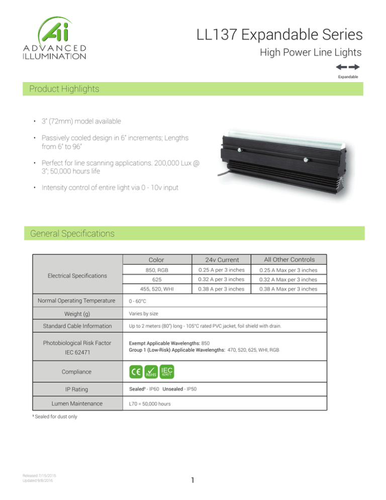
• 3” (72mm) model available
• Passively cooled design in 6” increments; Lengths from 6” to 96”
• Perfect for line scanning applications. 200,000 Lux @ 3”; 50,000 hours life
• Intensity control of entire light via 0 - 10v input
General Specifications
Electrical Specifications
Normal Operating Temperature
Weight (g)
Color
24v Current
All Other Controls
850, RGB
0.25 A per 3 inches
0.25 A Max per 3 inches
625
0.32 A per 3 inches
0.32 A Max per 3 inches
455, 520, WHI
0.38 A per 3 inches
0.38 A Max per 3 inches
0 - 60°C
Varies by size
Standard Cable Information
Up to 2 meters (80”) long - 105°C rated PVC jacket, foil shield with drain.
Photobiological Risk Factor
Exempt Applicable Wavelengths: 850
Group 1 (Low-Risk) Applicable Wavelengths: 470, 520, 625, WHI, RGB
IEC 62471
Compliance
IP Rating
Lumen Maintenance
Sealed¹ - IP60 Unsealed - IP50
L70 = 50,000 hours
¹ Sealed for dust only
Released 7/15/2015
Updated 9/8/2016
1
LL137 Expandable Series
Mechanical Specifications
34.9
(1.37)
3.2
(.13)
SEE CHART
Part #
115.5
(4.55)
“F” LENS
96.5
(3.80)
“D” LENS
102.8
(4.05)
“E” LENS
1.0
(.04)
M6 NUT CHANNEL
(HARDWARE INCLUDED)
55.8
(2.20)
92.7
(3.65)
“G” LENS
40.3
(1.58)
OPTIONAL IC HOLE LOCATION
69.8
(2.75)
7.0
(.28)
Length in mm (inches)
LL137X03
76
(3)
LL137X06
152
(6)
LL137X12
305
(12)
LL137X18
457
(18)
LL137X24
610
(24)
LL137X30
762
(30)
LL137X36
914
(36)
LL137X42
1067
(42)
6” Increments up to a max of 96” with the
exception of a 3” length model
50.2
(1.98)
“X” refers to the lens type: D,E,F,G
DIMENSIONS ARE IN MILLIMETERS (INCHES)
Part Number Key
Model
Lens
Type
Lighted
Length
Spectral
Wavelength
Connector/
Control
LL137
X
XX
XXX
XX
LL137
D
E
F
G
3” model available
as well as 6”
increments
up to 96”
(blue) 455
(green) 530
(red) 625
(infra-red) 850
(all colors) RGB
(white) WHI
C1
IC 1
24v
Ex: LL137E12-455C1
LL137G24-625IC
1
Stock Product: shipped next day
IC option (see page 4 for detail) not
available with 3” model
Build to Order:
LL137E12-WHI24
shipped within two weeks
Connector | Control Options
C1 Connector
IC
For use with:
DCS Series
Controllers
Released 7/15/2015
Updated 9/8/2016
24
Flying/tinned leads
Please see page 4
for IC information
Powered with:
24V power supply
2
Lens
Working Distance
Beam Width
D
50mm (2”)
3mm (.13”)
E
75mm (3”)
5mm (.18”)
F
150mm (6”)
8mm (.3”)
G
300mm (12”)
20mm (.8”)
600mm (24”)
38mm (1.5”)
900mm (36”)
56mm (2.2”)
1200mm (48”)
74mm (2.9”)
LL137 Expandable Series
Optical Performance
Intensity Distribution
Optical measurement taken using LL137E12-WHI24
60-80%
80-100%
20-40%
40-60%
10-20%
0-10%
Area of Illuminance & Intensity
Working Area (FWHM)
@ Working Distance
Light Output
304 (mm)
@75 mm
Irradiance (W/M²): Min 824.5; Typ 970
Illuminance (kLux): Min 238 ; Typ 280
Operation and Wiring
24 Volt
Optional M12 Pinout
Pin
(M12)
Function
Wire
Color
1
+24 VDC
Brown
2
N/A
White
3
GND
Blue
4
N/A
Black
4
5
3
1
2
male
5-position
Released 7/15/2015
Updated 9/8/2016
3
LL137 Expandable Series
IC Control
The IC option allows for control of intensity on each 6” (152mm) section of BL138, BL168, LL137
and LL167 only. Fig. 1 shows 5 segments of 6” (152mm) BL138 with IC adjustment holes.
Camera
Brightest
Brighter
Least Bright
Brighter
Brightest
Optional IC
adjustment hole
locations
(fig. 1)
Controlling each 6” (152mm) section independently and making the center of the line less bright and
the outside of the immediate camera viewing radius brighter ultimately results in better imaging.
Better imaging occurs because the camera can see very well in it’s area of focus, but outside that
area the camera doesn’t focus as well without brighter illumination.
Ai recommends using IC adjustment holes for aforementioned lights over 24” (610mm) long.
All other lighting products that have an IC option have the IC control located on the cable. (see fig. 2)
IC CONTROL ON ALL
OTHER PART NUMBERS
Standard IC control on all
other lighting products
(built into cable)
(fig. 2) Released 7/15/2015
Updated 9/8/2016
4
LL137 Expandable Series
Warranty Information
Every Advanced illumination, Inc. (Ai) product is thoroughly inspected and tested before leaving the factory.
Products are warranted to be free of defects in workmanship and materials for a period of two years from the
original date of purchase. Should a defect develop during this period, please contact Ai Customer Service or your
Ai distributor for a Return Merchandise Authorization (RMA), and return the complete product, freight prepaid, to Ai.
If a defect is found, Ai will - at our discretion - repair or replace the product without charge. Ai claims no liability for
any implied warranties, including “merchantability” and “fitness for a specific purpose.”
Electromagnetic Compatibility
This product was tested and complies with the regulatory requirements and limits for electromagnetic compatibility
(EMC) as stated in the product specifications. These requirements and limits are designed to provide reasonable
protection against harmful interference only when the product is operated in its intended industrial electromagnetic
environment. To minimize the potential for electromagnetic interference or unacceptable performance degradation,
install and use this product in strict accordance with the instructions in the product documentation.
Customer Service
For information on existing orders, or to make an order adjustment, contact us Monday through Friday 8:00 am to
5:00 pm, EST or send an email to orders@advill.com.
Company Information
Advanced Illumination
440 State Garage Road, Rochester VT. 05767
Phone: 802.767.3830
Fax: 802.767.3831
Email: info@advancedillumination.com
Web: advancedillumination.com
© 2015 Advanced Illumination Inc. All rights reserved
Released 7/15/2015
Updated 9/8/2016
5


