Understanding RIM Inputs - Phoenix Broadband Technologies
advertisement

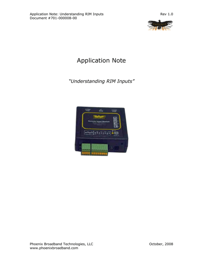
Application Note: Understanding RIM Inputs Document #701-000008-00 Rev 1.0 Application Note “Understanding RIM Inputs” Phoenix Broadband Technologies, LLC www.phoenixbroadband.com October, 2008 Application Note: Understanding RIM Inputs Document #701-000008-00 Rev 1.0 Purpose This document explains the circuit structure of the Phoenix Broadband RIM module and discusses considerations for interfacing to contact closure as well as analog input signals. Background The PBT-RIM series of products are Remote Input Modules that expand the number of monitored inputs in a ContactAgent remote monitoring system. Each RIM module adds 6 monitorable inputs to the ContactAgent system. Each input can monitor for a digital state change (contact closure, logic state, etc), or it can make analog DC and AC RMS voltage measurements on the input signal. In the digital input mode, each input’s threshold voltage (the voltage at which an input is considered to have changed from “OFF” to “ON”) is user programmable. In the analog input modes, the user can specify alarm thresholds for the measured DC or AC input signal. When interfacing the RIM module to any type of circuit other than contact closure devices (relay contacts, switch contacts, etc), the user should give careful consideration to input characteristics of the RIM as well as the output characteristics of the device being interfaced. The RIM Input Circuit Each of the 6 RIM input circuits is a resistive voltage divider as shown in the diagram at the right. The input to each voltage divider is the signal to be measured, and the output of each divider is applied to one of the analog-to-digital converter inputs of the RIM’s microcontroller. The resistor values have been selected so that input voltages of -12VDc to +12VDC will result in A-D input voltages of 0 to 3.3VDC. The resistor values are high enough to ensure that over-voltages on the inputs will be harmlessly clamped to a safe voltage by the microcontroller’s input protection diodes. 3.3 VDC 2.7K, 1% 10K, 1% A-D Converter Input Terminal 3.6K, 1% Digital Input Applications The most common application for the RIM module is to monitor the state of a contact-type switch device and generate an alarm when the switch state changes out of its “normal” state. The contact closure device to be interfaced is connected between one of the available inputs and an available system “Ground” terminal. In the digital input mode, the RIM measures the input voltage, and any voltage above 1.0VDC is considered to be the “Open” state, while anything less that 1.0 VDC is considered “Closed”. Thus, when the monitored contacts change state from “Open” to “Closed”, the voltage at the input of the RIM will change from 1.85VDC to approximately 0VDC, and the state change will be detected. Phoenix Broadband Technologies, LLC www.phoenixbroadband.com October, 2008 Application Note: Understanding RIM Inputs Document #701-000008-00 Rev 1.0 Another possible digital interface situation involves connecting the RIM to a digital voltage source such as a logic gate. In this case, care must be taken to ensure that the input device can “sink” enough DC current to ensure that the input voltage drops below 1.0VDC. an examination of the circuit shows that the current sinking requirement is very low, on the order of 300uA, but it should be kept in mind nonetheless. Analog Input Applications Interfacing to analog voltage sources is a bit more tedious, as accurate measurements will only be made if the source resistance of the driving voltage is low compared to the input resistance of the RIM. As the RIM input resistance is about 11K ohms, the voltage measurement error for a 1K source voltage resistance will be about 10%, about 1% for a 100 ohm source, etc. RMS Measurement Considerations The RIM is capable of making true RMS measurements of an AC input signal. This is done by taking several dozen voltage samples of the input, evenly spaced and close enough to each other in time to discern typical waveshape anomalies over the course of at least one complete cycle. All the samples are then fed through an RMS calculation (Root of the Mean of the signal Squares) to determine the RMS value of the input AC waveform. The RMS mode is primarily intended for measuring AC voltages that are proportional to the utility company AC power. The bandwidth of the function is only 150Hz or so, and there are some considerations for how the signal is coupled to the RIM inputs. The RMS mode assumes that the AC input signal will be driven from the output of a transformer, which will cause the DC input of the RIM to swing around 0VDC. If the input is not a transformer, then the DC voltage might be non-zero and the RMS reading will have an error component. Whatever the driving signal source for RMS measurements, care should be taken to consider the effects of the finite input resistance as well as the 0VDC input requirement. Conclusion The RIM module is a powerful and flexible expansion enhancement to the ContactAgent system. Users will undoubtedly find novel and clever uses for the device. This document should help with those endeavors. Phoenix Broadband Technologies, LLC www.phoenixbroadband.com October, 2008


