Design and Programming for Single Phase Induction Motor
advertisement

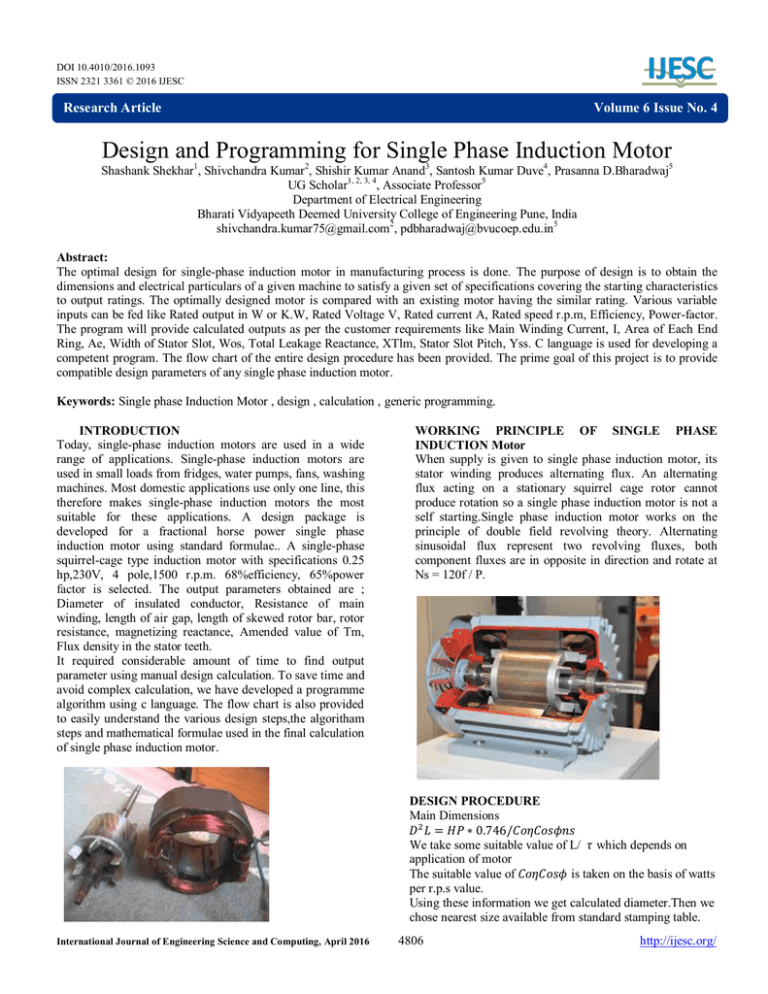
DOI 10.4010/2016.1093 ISSN 2321 3361 © 2016 IJESC Research Article Volume 6 Issue No. 4 Design and Programming for Single Phase Induction Motor Shashank Shekhar1, Shivchandra Kumar2, Shishir Kumar Anand3, Santosh Kumar Duve4, Prasanna D.Bharadwaj5 UG Scholar1, 2, 3, 4, Associate Professor 5 Department of Electrical Engineering Bharati Vidyapeeth Deemed University College of Engineering Pune, India shivchandra.kumar75@gmail.com2, pdbharadwaj@bvucoep.edu.in5 Abstract: The optimal design for single-phase induction motor in manufacturing process is done. The purpose of design is to obtain the dimensions and electrical particulars of a given machine to satisfy a given set of specifications covering the starting characteristics to output ratings. The optimally designed motor is compared with an existing motor having the similar rating. Various variable inputs can be fed like Rated output in W or K.W, Rated Voltage V, Rated current A, Rated speed r.p.m, Efficiency, Power-factor. The program will provide calculated outputs as per the customer requirements like Main Winding Current, I, Area of Each End Ring, Ae, Width of Stator Slot, Wos, Total Leakage Reactance, XTlm, Stator Slot Pitch, Yss. C language is used for developing a competent program. The flow chart of the entire design procedure has been provided. The prime goal of this project is to provide compatible design parameters of any single phase induction motor. Keywords: Single phase Induction Motor , design , calculation , generic programming. INTRODUCTION Today, single-phase induction motors are used in a wide range of applications. Single-phase induction motors are used in small loads from fridges, water pumps, fans, washing machines. Most domestic applications use only one line, this therefore makes single-phase induction motors the most suitable for these applications. A design package is developed for a fractional horse power single phase induction motor using standard formulae.. A single-phase squirrel-cage type induction motor with specifications 0.25 hp,230V, 4 pole,1500 r.p.m. 68%efficiency, 65%power factor is selected. The output parameters obtained are ; Diameter of insulated conductor, Resistance of main winding, length of air gap, length of skewed rotor bar, rotor resistance, magnetizing reactance, Amended value of Tm, Flux density in the stator teeth. It required considerable amount of time to find output parameter using manual design calculation. To save time and avoid complex calculation, we have developed a programme algorithm using c language. The flow chart is also provided to easily understand the various design steps,the algoritham steps and mathematical formulae used in the final calculation of single phase induction motor. WORKING PRINCIPLE OF SINGLE PHASE INDUCTION Motor When supply is given to single phase induction motor, its stator winding produces alternating flux. An alternating flux acting on a stationary squirrel cage rotor cannot produce rotation so a single phase induction motor is not a self starting.Single phase induction motor works on the principle of double field revolving theory. Alternating sinusoidal flux represent two revolving fluxes, both component fluxes are in opposite in direction and rotate at Ns = 120f / P. DESIGN PROCEDURE Main Dimensions We take some suitable value of L/ which depends on application of motor The suitable value of is taken on the basis of watts per r.p.s value. Using these information we get calculated diameter.Then we chose nearest size available from standard stamping table. International Journal of Engineering Science and Computing, April 2016 4806 http://ijesc.org/ STATOR DESIGN i) Number of turns in main winding: Stator induced voltage E= 4.44fϕmTmKwm Where Tm = number of turns in the running winding, Kwm= winding factor for the running winding. Number of turns in the running winding Where, фm = flux per pole ф = flux density x slots per pole x x Wb The number of turns per series pole for the main (running) winding= Tmp ii) Running Winding Conductors Current carried by each running winding conductor Irated=hpx0.746/Vηcosϕ Efficiency and power factor for single phase motors Area of running winding conductor am = Imδ Where δ is the current density in Amps/mm2 Conductor size for the running winding can be calculated as follows- Therefore area of running winding conductor = IRatedδ Diameter size of running winding conductor d= ¡¡¡)Starting winding The stating winding is designed for maximum torque per ampere of starting current.To calculate starting torque and current,the rotor resistance is increased by 17.5% to take into account the skin effect. Therefore,total resistance in terms of main winding Rm=rsm+1.175 r’rm at 20 . Total impedance at 20 Zm= Auxiliary winding reactance Xla=Xlm/((Is/Ism)^21) Resistance of auxiliary winding Ra=(Rm+Zm(Is/Ism))/((Is/Ism)^2-1) Auxiliary winding conductor section aa= Diameter of bare conductor = In capacitor start method reactance of the capacitor Xc=Xla+((Ra*Rm)/(Zm+Xlm)) CALCULATION Specification : 1. 2. 3. 4. 5. 6. 7. 8. 9. 10. 11. 12. 0.25 HP 1 Phase 50 Hz 230 V 1450 rpm 2.253 Amp 4 pole Starting Torque Pull out Torque Efficiency 61 % Power Factor 59 % Resistance start and capacitance start Induction Motor International Journal of Engineering Science and Computing, April 2016 MAIN DIMENSIONS ASSUMPTION: Co = 12.2 For watt/rps = 7.46 from Table L/Tp = 1 , for overall good design Calculated Value D2L = 611.475 D = 3.6 Inch Choosing nearest size available from the standard stamping table i.e. 138 M of G.K.W. for which D = 3.5Inch = 8.9 cm for required D2L , L = 7.72 cm. STATOR DESIGN ASSUMPTION: Stacking factor = 0.95 Flux density in stator teeth = 1.1 wb/ Kw main = 0.8 Stator induced EMF = 0.95 v Main winding current density = 4 A/mm Resistivity of conductor material at 75 c = 0.021 Ω m and at 20 c= 0.017 Ωm 3 coil per pole RESULT: 28 Stator slot with parallel sided teeth and tapred slots Wts = 0.1425 inch = 0.362 cm = width of stator teeth DO = OUTER Diameter = 13.81 cm Depth of stator slots = 0.573 inch =1.455cm Flux density in stator core = 1.39 Number of turns in main winding = 606 Turns in series per pole = 152 Therefor amended value of Tm = 4×152 = 608 3 Coile per pole having 30 , 54 and 68 turns for sinusoidal flux distribution Conductor = 0.56mm Calculated diameter of main winding conductor = 0.3466mm Available standard size of conductor = 0.85mm Diameter for insulated conductor = 0.912mm Slot space factor = 0.4038<0.5 Lmt = 29.426cm Resistance of main winding at 20°c = 6.62Ω and at 75°c = 5.36Ω ROTOR DESIGN: According to selected stamping Rotor outer diameter = 3.5inch = 8.9cm Rotor inner diameter = 3inch/4 = 1.9cm Number of slots = 20 which are closed type rectangular slot 4807 http://ijesc.org/ Results Length of air gap = 0.3mm(by empirical formula) To give air gap of 0.3mm rotor diameter = 8.84cm Area of rotor slots = 0.28cm2 and area of rotor bars = 24mm2 Total stator copper section = 690mm2 Area of end rings = 38.2mm2 End rings depth = 8mm(according to availability) and end rings thickness = 4.8mm End rings enner diameter = 7.1cm End rings outer diameter = 8.7cm and mean diameter = 7.9cm Gap extension coefficient for stator , Kgss = 1.118 and for rortor , Kgsr = 1.036 Kg = 1.118×1.036 = 1.158 Length of skewed rotor bar = 7.84cm Rotor resistance = 9.76Ω at 75°c and 7.9Ω at 20°c STARTING WINDING : (a) FOR RESISTANCE SPLIT PHASE Auxiliary winding reactance Xla = 21.9 Average Lmt for auxiliary winding = 35.124cm No. of turns in series = 456 Resistance of auxiliary winding = 49.209Ω Diameter of base conductor = 0.28mm (available) Impedance of auxiliary winding under locked rotor = 53.88Ω Auxiliary winding locked rotor current = 4.27A Current density in auxiliary winding = 67.025 A/mm2 Starting torque = 1.88 N-M Starting torque/Full load torque = 1.15 (b) FOR CAPACITANCE START Capacitance of capacitor = 92.29 µF Starting torque = 4.307 N-M = 264 % of full load torque Auxiliary winding impedance = 50.79Ω Locked rotor current of auxiliary winding = 4.528 Amp Current density in auxiliary winding = 71.08 A/mm2 Starting current = 9.76 Amp = 4.2×full load current. We have done programming in C language using the formulae and optimum results obtained by manual calculation.The flowchart is as follows- FLOWCHART International Journal of Engineering Science and Computing, April 2016 4808 http://ijesc.org/ CONCLUSION The result obtained from the output of programme is almost equal to the manual calculation. This programme will be used by students to get instant calculated resuls for design of single phase induction motor International Journal of Engineering Science and Computing, April 2016 The screen shot of the above said programme has been included to easily understand the input and output results which is approximate manual calculation. 4809 http://ijesc.org/ REFERENCES [1] M. V.K, Principles of Electrical Machines, India: S. Chand, 2002. [2] T. a. Chand, A Text Book of Electrical Technology, India : S. Chand , 2005. [3] F. A. S. U. Charles K., Electric Machinery, New York: Mc Graw Hill, 2003. [4] J. B., Electrical and Electronic Principles and Technology, New York: Oxford , 2003. [5] A. R.K., Principles of Electrical Machine Design, India: S.K. karataria &Son, 2007. Shashank Shekhar B.Tech student Electrical Engineering BVDUCOEP Santosh Kumar Duve B.Tech student Electrical Engineering BVDUCOEP Shivchandra Kumar B.Tech student Electrical Engineering BVDUCOEP Shishir kumar Anand B.Tech student Electrical Engineering BVDUCOEP Prasanna D.Bharadwaj Associate Professor Electrical Engineering BVDUCOEP International Journal of Engineering Science and Computing, April 2016 4810 http://ijesc.org/


