Picking the Right Sample-and-Hold Amp for Various Data
advertisement

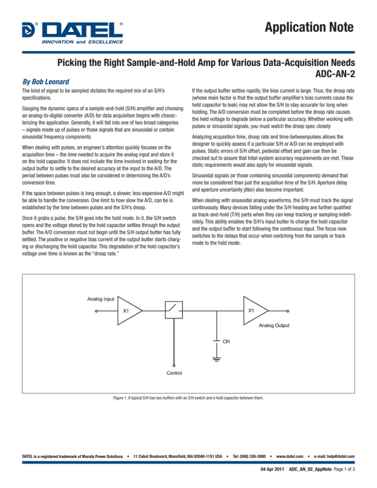
® Application Note ® Picking the Right Sample-and-Hold Amp for Various Data-Acquisition Needs ADC-AN-2 By Bob Leonard The kind of signal to be sampled dictates the required mix of an S/H’s specifications. Gauging the dynamic specs of a sample-and-hold (S/H) amplifier and choosing an analog-to-digital converter (A/D) for data acquisition begins with characterizing the application. Generally, it will fall into one of two broad categories – signals made up of pulses or those signals that are sinusoidal or contain sinusoidal frequency components. When dealing with pulses, an engineer’s attention quickly focuses on the acquisition time – the time needed to acquire the analog input and store it on the hold capacitor. It does not include the time involved in waiting for the output buffer to settle to the desired accuracy at the input to the A/D. The period between pulses must also be considered in determining the A/D’s conversion time. If the space between pulses is long enough, a slower, less expensive A/D might be able to handle the conversion. One limit to how slow the A/D, can be is established by the time between pulses and the S/H’s droop. Once it grabs a pulse, the S/H goes into the hold mode. In it, the S/H switch opens and the voltage stored by the hold capacitor settles through the output buffer. The A/D conversion must not begin until the S/H output butter has fully settled. The positive or negative bias current of the output butter starts charging or discharging the hold capacitor. This degradation of the hold capacitor’s voltage over time is known as the “droop rate.” If the output buffer settles rapidly, the bias current is large. Thus, the droop rate (whose main factor is that the output buffer amplifier’s bias currents cause the hold capacitor to leak) may not allow the S/H to stay accurate for long when holding. The A/D conversion must be completed before the droop rate causes the held voltage to degrade below a particular accuracy. Whether working with pulses or sinusoidal signals, you must watch the droop spec closely Analyzing acquisition time, droop rate and time-betweenpulses allows the designer to quickly assess if a particular S/H or A/D can be employed with pulses. Static errors of S/H offset, pedestal offset and gain can then be checked out to assure that total-system accuracy requirements are met. These static requirements would also apply for sinusoidal signals. Sinusoidal signals (or those containing sinusoidal components) demand that more be considered than just the acquisition time of the S/H. Aperture delay and aperture uncertainty jitter) also become important. When dealing with sinusoidal analog waveforms, the S/H must track the signal continuously. Many devices falling under the S/H heading are further qualified as track-and-hold (T/H) parts when they can keep tracking or sampling indefinitely. This ability enables the S/H’s input butter to charge the hold capacitor and the output buffer to start following the continuous input. The focus now switches to the delays that occur when switching from the sample or track mode to the hold mode. Figure 1. A typical S/H has two buffers with an S/H switch and a hold capacitor between them. DATEL • 11 Cabot Boulevard, Mansfield, MA 02048-1151 USA • Tel: (508) 339-3000 • www.datel.com 04 Apr 2011 • e-mail: help@datel.com ADC_AN_02_AppNote Page 1 of 3 ® Application Note ® Applications in which the analog input is tracked itself fall into two groups. In the first, the analog input must be held upon receipt of a given signal or detection of a particular physical occurrence. In the second, the analog input is sampled periodically. sample to hold mode is given by a S/H aperture delay specification of 6ns, the maximum frequency of the analog input tolerable to produce 12 bits to ±1/2-LSB is: 2.44mV = slew rate = 2pi fV 6ns or Random Sampling For applications where dynamic signals must go into the hold mode upon detection, the aperture-delay specification of the S/H is of key importance. The aperture delay of a S/H or T/H is defined as the delay that occurs from the point at which the S/H receives the command to go into the hold mode to the time it actually does go into holding the analog input. The analog input to be digitized by the A/D incurs an inaccuracy due to the aperture delay time of the internal S/H switch. The desired signal to be held and digitized will differ from the actual signal based upon the slew rate of the analog input signal. f= 2.44mV = 6.47kHZ 6ns (2pi 0V) Applications that require a signal to be detected before going into hold thus have their maximum frequency limited initially by the aperture delay time of the S/H. Periodic Sampling slew rate = dV = 2pi fV dt Many sinusoidal applications do not require detection of a physical phenomenon before going into hold mode. In fact, the majority require a repetitive sampling period to identify the signal frequency being digitized. The minimum required sampling frequency of the A/D subsystem is dictated by the Nyquist rate as twice the signal frequency being digitized. In actuality, the sampling of analog frequencies can be four to five times the frequency of the analog input being digitized. Where dV is equal to the tolerable voltage change. If a ± 10V (10-V full scale, 20-V full-scale-range) signal is to be digitized to ±1/2-LSB at 12 bits, 1/2-LSB accuracy is equal to 2.44 mV. If the change in time (dt) in going from the Applications requiring periodic sampling are often classified as digital-signal processing (DSP) applications. In DSP, since periodic sampling is the rule in identifying the input signal, designers can take advantage of the known The deviation between the desired signal and the actual signal held and digitized is determined from the slew rate of the analog input. The tolerable slew rate for a desired accuracy is the same as the tolerable change in voltage allowed over time. It can be defined as: Specified Error Band Overshoot Final Voltage FS Capacitor Charging VC Aquisition Time Sample Command Time Switching Time Delay Figure 2. S/H acquisition time ends when the full-scale voltage stays within the error band. DATEL • 11 Cabot Boulevard, Mansfield, MA 02048-1151 USA • Tel: (508) 339-3000 • www.datel.com 04 Apr 2011 • e-mail: help@datel.com ADC_AN_02_AppNote Page 2 of 3 ® Application Note ® repetitive delay (aperture delay of the S/H in going from the sample (or track) mode to the hold mode. Using Fourier transforms, the digitized signal is analyzed for its frequency components; radar, sonar and imaging are among the many applications that fall under this heading. Another S/H specification, aperture uncertainty Jitter), defines the uncertainty of the aperture-delay specification. If there is 6-ns delay in going from the sample mode to actual hold mode, this delay will be repetitive, and it won’t affect identification of the input frequency. The delay can be compensated for by going into the hold mode 6ns earlier if the phase delays of the frequency to be identified are important. The uncertainty about whether or not the delay is exactly 6ns is mostly due to noise in the logic threshold of the switch when going from sample to hold. A data-acquisition system designer is able to compensate for the known delay with periodic sampling, or by going into the hold mode earlier. Referring to the slew rate calculation mentioned earlier, if the S/H is put into the hold mode earlier in anticipation of the known delay, or if the delay would only represent itself as a tolerable phase shift for repetitive signals, the aperture uncertainty is now the limiting factor (dt) of the maximum input slew rate or frequency. An aperture uncertainty of 50 ps for a 12-bit linear S/H will yield a maximum frequency of: The slew rate and maximum frequency that can be digitized is much higher than that possible when using the aperture delay specification for random signals. But the acquisition time of the S/H must still be observed between samples. Slew Rate Spec A monolithic S/H may indicate an aperture delay or aperture uncertainty indicating initial capability to digitize a widebandwidth signal. An investigation into the slew-rate specification will confirm if this is possible. The maximum frequency on a 10-V input before slew-rate limiting occurs on the input signal is given by: f = slew rate 2pi 10V The gain-bandwidth specification can be checked to see if any gain loss could occur at the frequency of interest with: 1 A= f= 2.44mV = 776.67kHZ 50 ps × 2 pi 10V DATEL 11 Cabot Boulevard, Mansfield, MA 02048-1151 USA 2 Summary slew rate = 2.44mV/50 ps = 2pi fV: or f 1+( –3dB bandwidth ) Obtaining dynamic performance of data acquisition designs requires careful analysis of sample-hold specifications. Assessment of the end-use application will dictate which parameters will determine a designer’s system limitations. . makes no representation that the use of its products in the circuits described herein, or the use of other technical information contained herein, will not infringe upon existing or future patent rights. The descriptions contained herein do not imply the granting of licenses to make, use, or sell equipment constructed in accordance therewith. Specifications are subject to change without notice. ITAR and ISO 9001/14001 REGISTERED www.datel.com • e-mail: help@datel.com 04 Apr 2011 ADC_AN_02_AppNote Page 3 of 3

