VR t( )= RIR t( ) VR s( )= RIR s( ) VC t( )= QC t( ) VC t( )= IC t( ) sVC s
advertisement
MTH 352
Real World LC Components
Prof. Townsend (analysis by Patricia Mellodge)
Fall 2008
Real world capacitors and inductors include the ideal model along with resistors and, perhaps,
inductors and capacitors. This document addresses the effect on the voltage across the primary
resistor in both parallel and series RLC circuits due to using real world models. There are a
number of such models but we will use the ones that only introduce additional resistances in the
circuits to keep the differential equations to second order.
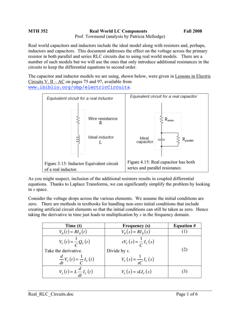
The capacitor and inductor models we are using, shown below, were given in Lessons in Electric
Circuits V. II – AC on pages 75 and 97, available from
www.ibiblio.org/obp/electricCircuits.
Figure 3.15: Inductor Equivalent circuit
of a real inductor.
Figure 4.15: Real capacitor has both
series and parallel resistance.
As you might suspect, inclusion of the additional resistors results in coupled differential
equations. Thanks to Laplace Transforms, we can significantly simplify the problem by looking
in s space.
Consider the voltage drops across the various elements. We assume the initial conditions are
zero. There are methods in textbooks for handling non-zero initial conditions that include
creating artificial circuit elements so that the initial conditions can still be taken as zero. Hence
taking the derivative in time just leads to multiplication by s in the frequency domain.
Time (t)
VR ( t ) = RI R ( t )
1
VC ( t ) = QC ( t )
C
Take the derivative.
d
1
VC ( t ) = I C ( t )
dt
C
d
VL ( t ) = L I C ( t )
dt
Real_RLC_Circuits.doc
Frequency (s)
VR ( s ) = RI R ( s )
1
sVC ( s ) = I C ( s )
C
Divide by s.
1
VC ( s ) =
IC ( s )
sC
VL ( s ) = sLI C ( s )
Equation #
(1)
(2)
(3)
Page 1 of 6
In the table below are the circuit diagrams for series and parallel RLC circuits. The diagrams
show the circuits, both with ideal and the models we are using for capacitors and inductors, in
both the time domain and the frequency domain.
Time
Real_RLC_Circuits.doc
Frequency (s)
Page 2 of 6
As indicated above, time domain analysis of these circuits results in coupled differential
equations. We know that the use of Laplace Transforms takes differential equations and turns
them into algebraic equations. The analysis of the frequency domain circuits is algebra intensive
so I used a symbolic algebra program, LiveMathMaker (nee Theorist), to do the work for me.
The results are shown in the diagram below.
Real_RLC_Circuits.doc
Page 3 of 6
The words messy equations in the above are the titles of groups of hidden algebraic
manipulations in LiveMathMaker, viewable upon request.
Consider the results for the parallel circuit. The final equation is
Bs 2 + Ds + A V ( s ) = Gs 2 + Fs + E I s ( s )
(4)
Recall that the current source is represented by
I s ( t ) = I 0 sin (! t )
(5)
(
)
(
)
Its Laplace Transform is
" ! %
Is ( s) = I0 $ 2
# s + ! 2 '&
(6)
We can then solve equation (4) for the Laplace Transform of the voltage
Gs 2 + Fs + E " ! %
V ( s) = I0
$
'
Bs 2 + Ds + A # s 2 + ! 2 &
(
(
)
)
(7)
Use the TI-89 Expand() command or use a partial fraction expansion to rewrite equation (7) as a
collection of identifiable inverse transforms, then use the Laplace Transform table to find the
voltage across all the branches as a function of time. The equation for the series RLC
configuration follows the same analysis with the result being the current through the elements in
series as a function of the applied voltage, Vs ( t ) = V0 sin (! t ) .
We can also recover the differential equation for the system in the time domain. Start with
equation (4). Recall that multiplication by s in the frequency domain is equivalent to a derivative
in the time domain. Therefore equation (4) looks like the following in the time domain.
d2
d
d2
d
B 2 V ( t ) + D V ( t ) + AV ( t ) = G 2 I s ( t ) + F I s ( t ) + EI s ( t )
(8)
dt
dt
dt
dt
Since we know the time dependence of the current source, I s ( t ) = I 0 sin (! t ) , equation (8)
becomes
d2
d
B 2 V ( t ) + D V ( t ) + AV ( t ) = I 0 !G" 2 sin (" t ) + F" cos (" t ) + E sin (" t )
(9)
dt
dt
{
}
The right hand side of equation (9) is just a sine or cosine wave with a phase shift.
d2
d
B 2 V ( t ) + D V ( t ) + AV ( t ) = I 0! cos (" t # $ )
dt
dt
where α is a multiplier that is a function of E, F, G, and ω.
(10)
We find the values of the phase shift, δ, and amplitude factor, α, by using a trig identity.
Real_RLC_Circuits.doc
Page 4 of 6
Given
! cos (" t # $ ) = ( E # G" 2 ) sin (" t ) + F" cos (" t )
(11)
we use the trig identity
! cos (" t # $ ) = ! {sin ($ ) sin (" t ) + cos ($ ) cos (" t )}
(12)
to arrive at,
! sin (" ) = E # G$ 2
and
! cos (" ) = F#
(13)
(14)
Dividing equations (13) and (14) gives us
E " G# 2
tan (! ) =
F
(15)
The appropriate quadrant for δ is determined by looking at the signs of equations (13) and (14).
Squaring (13) and (14), adding the results, then taking the square root of the result gives
!=
( E " G# )
2 2
+ F2
(16)
We now rewrite equation (10) so it looks like (almost) an RLC parallel circuit with effective
values of R, L and C.
! B d2
!D d
!A
V (t ) +
V (t ) +
V ( t ) = I 0! cos (! t # $ )
(17)
2
" dt
" dt
"
Define
Ceff !
"B
,
#
Reff !
"
,
#D
Leff !
"
,
#A
and
! " # t0
(18)
Then equation (17) becomes
d2
1 d
1
d
Ceff 2 V ( t ) +
V (t ) +
V ( t ) = I 0 sin {! ( t " t 0 )}
dt
Reff dt
Leff
dt
(19)
which, except for the shift in time, is the same as the equation for a simple parallel RLC circuit.
d 2v 1 d
1
di
C 2 +
v+ v= s
(20)
dt
R dt
L
dt
with is ( t ) = I 0 sin (! t ) .
A similar analysis can be performed for the series RLC circuit case.
Real_RLC_Circuits.doc
Page 5 of 6
Since we assumed zero initial conditions to arrive at equation (13) via Laplace Transform
methods, the effective circuit described by equation (13) will result in non-zero initial conditions
due to the time shift in the current source.
The impact of using our models of real world capacitors and inductors leads not only to effective
inductors and capacitors, as provided by the left hand side of equation (10), but it also modifies
the current source in amplitude and phase, as provided by the right hand side of equation (10).
For the parallel RLC circuit case, the voltage across the primary resistor is found by solving
equation (7), then back transforming or by solving equation (10) using conventional time
dependent techniques. For the series RLC circuit case, we find the current through the resistor
then multiply by the resistance, R, to find the voltage across the resistor.
I am deeply indebted to Patricia Mellodge for providing the above analysis. She turned my
intractable problem into one that we could analyze and understand.
Real_RLC_Circuits.doc
Page 6 of 6
