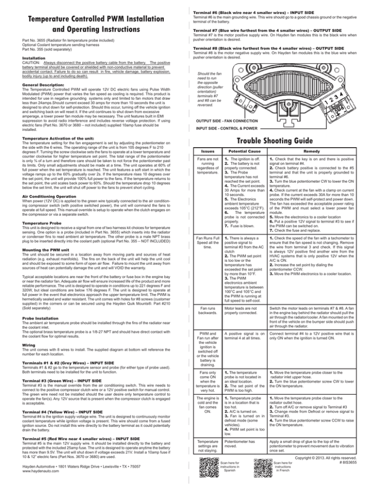
Temperature Controlled PWM Installation
and Operating Instructions
Part No. 3655 (Radiator fin temperature probe included)
Optional Coolant temperature sending harness
Part No. 355 (sold separately)
Installation
CAUTION: Always disconnect the positive battery cable from the battery. The positive
battery terminal should be covered or shielded with non-conductive material to prevent
accidental contact. Failure to do so can result in fire, vehicle damage, battery explosion,
bodily injury (up to and including death).
General Description:
The Temperature Controlled PWM will operate 12V DC electric fans using Pulse Width
Modulated (PWM) power that varies the fan speed as cooling is required. This product is
intended for use in negative grounding systems only and limited to fan motors that draw
less than 24amps.Should current exceed 30 amps for more than 10 seconds the unit is
designed to shut down for self-protection. Should this occur, turning off the vehicle ignition
and switching back on will reset it. If the unit continues to shut down from excessive
amperage, a lower power fan module may be necessary. The unit features built in EMI
suppression to avoid radio interference and includes reverse voltage protection. If using
electric fans (Part No. 3670 or 3680 – not included) supplied 10amp fuse should be
installed.
Temperature Activation of the unit:
The temperature setting for the fan engagement is set by adjusting the potentiometer on
the side with the 6 wires. The operating range of the unit is from 105 degrees F to 210
degrees F. Turning the screw clockwise sets the fans to operate at a lower temperature and
counter clockwise for higher temperature set point. The total range of the potentiometer
is only ¾ of a turn and therefore care should be taken to not force the potentiometer past
its limits. Only small adjustments should be made at a time. The unit operates at 60% of
full power when the set temperature is reached. The unit features a soft start in which the
voltage ramps up to the 60% gradually over 2s. If the temperature rises 10 degrees over
the set point, the unit will provide 100% full power to the fans. If the temperature returns to
the set point, the unit scales back power to 60%. Should the temperature drop 10 degrees
below the set limit, the unit will shut off power to the fans to prevent short cycling.
Terminal #6 (Black wire near 4 smaller wires) – INPUT SIDE
Terminal #6 is the main grounding wire. This wire should go to a good chassis ground or the negative
terminal of the battery.
Terminal #7 (Blue wire furthest from the 4 smaller wires) – OUTPUT SIDE
Terminal #7 is the motor positive supply wire. On Hayden fan modules this is the black wire when
pusher orientation is desired.
Terminal #8 (Black wire furthest from the 4 smaller wires) – OUTPUT SIDE
Terminal #8 is the motor negative supply wire. On Hayden fan modules this is the blue wire when
pusher orientation is desired.
Should the fan
need to run
the opposite
direction (puller
orientation)
terminals #7
and #8 can be
reversed.
OUTPUT SIDE - FAN CONNECTION
INPUT SIDE - CONTROL & POWER
Trouble Shooting Guide
Issues
Potential Cause
Remedy
Fans are not
running
regardless of
temperature.
1. The ignition is off.
2. The battery is not
properly connected.
3. The Probe
temperature has not
reached the set point.
4. The Current exceeds
30 Amps for more than
10 seconds.
5. The Electronics
ambient temperature
exceeds 105°C (212°F).
6.
The temperature
probe is not connected
properly.
7. Fuse is blown.
1. Check that the key is on and there is positive
signal on terminal #4.
2. Check battery positive is connected to the #5
terminal and that the unit is properly grounded to
terminal #6.
3. Turn the blue potentiometer CW to lower the ON
temperature.
4. Check current at the fan with a clamp on current
probe. If the current exceeds 30A for more than 10
seconds the PWM will self-protect and power down.
The fan has exceeded the acceptable power rating
of the PWM and must select a lower power fan
module.
5. Move the electronics to a cooler location
6. Put a positive 12V signal to terminal #3 to see if
the PWM can be switched on.
7. Check the fuse and replace.
Fan Runs Full
Speed all the
time.
1. There is always a
positive signal to
terminal #3 from the AC
clutch
2. The PWM set point
is too low or the
temperature has
exceeded the set point
by more than 10°F.
3. The PWM
electronics ambient
temperature is between
100°C and 105°C and
the PWM is running at
full speed to self-cool.
1. Check the speed of the fan with a tachometer to
ensure that the fan speed is not changing. Remove
the wire from terminal 3 and check. If this signal
is always 12V positive find another wire from the
HVAC systems that is only positive 12V when the
A/C is ON.
2. Increase the set point by dialing the
potentiometer CCW.
3. Move the PWM electronics to a cooler location.
Motor leads are not
properly connected.
Switch the motor leads on terminals #7 & #8. A fan
in the engine bay behind the radiator should pull the
air through the radiator/cooler. A fan mounted on the
front of the vehicle on the bumper side should push
air through the radiator.
PWM and
Fan run after
the vehicle
ignition is
switched off
or the vehicle
battery is
draining.
A positive signal is on
terminal 4 at all times.
Connect terminal #4 to a 12V positive wire that is
only ON when the ignition is turned ON.
Fans only
come ON
when the
temperature is
very hot.
1. The temperature
probe is not located in
an ideal location.
2. The set point of the
PWM is too high.
1. Move the temperature probe closer to the
radiator inlet upper hose.
2. Turn the blue potentiometer screw CW to lower
the ON temperature.
The engine is
cold and the
fan comes
ON.
1. Temperature probe
is in a location that is
too hot.
2. A/C is turned on.
3. Fan is turned on in
defrost mode (some
vehicles).
4. PWM set point is too
low.
1. Move the temperature probe closer to the
radiator outlet hose.
2. Turn off A/C or remove signal to Terminal #3
3. Change mode from Defrost or remove signal to
Terminal #3.
4. Turn the blue potentiometer screw CCW to raise
the ON temperature.
Temperature
settings are
not staying.
Potentiometer has
moved.
Apply a small drop of glue to the top of the
potentiometer to prevent movement due to vibration
once set.
Air Conditioning Operation
When power (12V DC) is applied to the green wire typically connected to the air conditioning compressor switch (with positive switched power), the unit will command the fans to
operate at full speed. This manual override is setup to operate when the clutch engages on
the compressor or via a separate switch.
Temperature Probe
This unit is designed to receive a signal from one of two harness kit choices for temperature
sensing. One option is a probe (included in Part No. 3655) which inserts into the radiator
or condenser fins to read ambient air temperature. The other probe is a male NPT brass
plug to be inserted directly into the coolant path (optional Part No. 355 – NOT INCLUDED)
Mounting the PWM unit
The unit should be secured in a location away from moving parts and sources of heat
radiation (e.g. exhaust manifolds). The fins on the back of the unit will help the unit cool
and should be exposed to some form of open air flow. Failure to mount the unit away from
sources of heat can potentially damage the unit and will VOID the warranty.
Typical acceptable locations are near the front of the battery or fuse box in the engine bay
or near the radiator fan. Adequate air flow will ensure increased life of the product and more
reliable performance. The unit is designed to operate in conditions up to 221 degrees F and
320W, but ideal conditions are below 176 degrees F. The unit is designed to operate at
full power in the event that electronics approach the upper temperature limit. The PWM is
hermetically sealed and water resistant. The unit comes with holes for #8 screws (customer
supplied) in the corners or can be secured using the Hayden Quik Mounts®. Part #210
(Sold separately)
Probe Installation
The ambient air temperature probe should be installed through the fins of the radiator near
the coolant inlet.
The optional brass temperature probe is a 1/8-27 NPT and should have direct contact with
the coolant flow for optimal results.
Wiring
The unit comes with 8 wires to install. The supplied diagram at bottom will reference the
number for each location.
Terminals #1 & #2 (Grey Wires) – INPUT SIDE
Terminals #1 & #2 go to the temperature sensor and probe (for either type of probe used).
Both terminals need to be installed for the unit to function.
Terminal #3 (Green Wire) – INPUT SIDE
Terminal #3 is the manual override from the air conditioning switch. This wire needs to
connect to the positive compressor clutch wire or a 12V positive switch for manual control.
The green wire need not be installed should the user desire only temperature control to
operate the fan(s). Any 12V source that is present when the compressor clutch is engaged
is acceptable.
Terminal #4 (Yellow Wire) – INPUT SIDE
Terminal #4 is the ignition supply voltage wire. The unit is designed to continuously monitor
coolant temperature while ignition voltage is present. This wire should come from a fused
ignition source. Do not install this wire directly to the battery terminal as it could potentially
drain the battery.
Terminal #5 (Red Wire near 4 smaller wires) – INPUT SIDE
Terminal #5 is the main 12V supply wire. It should be installed directly to the battery and
protected with the included 25amp fuse. The unit is designed to operate anytime the battery
has more than 9.5V. The unit will shut down if voltage exceeds 21V. Install a 10amp fuse if
10 & 12” electric fans (Part Nos. 3670 or 3680) are used.
Hayden Automotive • 1801 Waters Ridge Drive • Lewisville • TX • 75057
www.haydenauto.com
Fan runs
backwards.
Scan here for
instructions in
Spanish
Scan here for
instructions
in French
Copyright © 2013. All rights reserved.
# 8IS3655


