RA 95 512/07.02
RA 95 512/07.02
replaces: 03.93
Flushing and Boost Pressure Valve
with limitation of the flushing oil volume
for installation in closed circuits
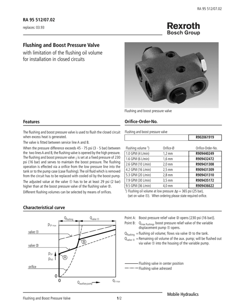
Flushing and boost pressure valve
Features
Orifice-Order-No.
The flushing and boost pressure valve is used to flush the closed circuit
when excess heat is generated.
The valve is fitted between service line A and B.
When the pressure difference exceeds 45 - 75 psi (3 - 5 bar) between
the two lines A and B, the flushing valve is opened by the high pressure.
The flushing and boost pressure valve ¡ is set at a fixed pressure of 230
psi (16 bar) and serves to maintain the boost pressure. The flushing
operation is effected via a orifice from the low pressure line into the
tank or to the pump case (case flushing). The oil fluid which is removed
from the circuit has to be replaced with cooled oil by the boost pump.
The adjusted value at the valve ➀ has to be at least 29 psi (2 bar)
higher than at the boost pressure valve of the flushing valve ➁.
Different flushing volumes can be selected by means of orifices.
Flushing and boost pressure valve
R902061919
Flushing volume 1)
Orifice-Ø
Orifice-Order-No.
1.0 GPM (4 L/min)
1,2 mm
R909440249
1.6 GPM (6 L/min)
1,6 mm
R909432472
2.6 GPM (10 L/min)
2,0 mm
R909431308
4.2 GPM (16 L/min)
2,5 mm
R909431309
5.3 GPM (20 L/min)
2,8 mm
R909431310
7.9 GPM (30 L/min)
3,5 mm
R909435172
9.5 GPM (36 L/min)
4,0 mm
R909436622
1) Flushing oil volume at low pressure ∆p = 365 psi (25 bar),
(set on valve ➀). When ordering please state required orifice.
Characteristical curve
Point A: Boost pressure relief valve ➁ opens [230 psi (16 bar)].
Point B: Qmax flushing, boost pressure relief valve of the variable
displacement pump ➀ opens.
Qflushing = flushing oil volume; flows via valve ➁ to the tank.
Qvalve ➀ = Remaining oil volume of the aux. pump; will be flushed out
via valve ➀ into the housing of the variable pump.
Qvalve ➀
Qflushing
pSP max
valve ➀
B
valve ➁
pSP
pND
A
Flushing valve in center position
Flushing valve adressed
orifice
0
0
Flushing and Boost Pressure Valve
Qauxiliary pump
qV max
1/2
Mobile Hydraulics
RA 95 512/07.02
Technical Data
Hydraulic circuit
Pump
Type
Pressure setting of the boost pressure valve
Opening pressure of the flushing valve
Mounting position
Seals
Weight (approx.)
Flushing and boost
pressure valve
230 psi (16 bar), fixed
∆p 45 - 75 psi (3 - 5 bar)
optional
FKM (fluor-caoutchouc)
3.7 lbs (1.7 kg)
Motor
B
2
1
T
A
Unit Dimensions
Before finalizing your design, please request a certified drawing.
Dimensions in inches and millimeters ( ).
1.34 (34)
1.38 (35)
2.52 (64)
0.79
(20)
1.77 (45)
3.54 (90)
3.94 (100)
DIA 0.59 (ø15);
0.04 (1) deep
DIA 0.33 (ø8,4)
T
1.57 (40)
3.94 (100)
4.88 (124)
Mounting face
0.87
(22)
1.57 (40)
2.36 (60)
Connections
A, B operating pressure
T
flushing oil return
A
1.57 (40)
7/8"-14 UNF-2B; 17 deep
7/8"-14 UNF-2B; 17 deep
B
The specified data is for product description purposes only and may not be deemed to be guaranteed unless expressly confirmed in the contract.
Mannesmann Rexroth Corporation
Industrial Hydraulics Division, 2315 City Line Road, Bethlehem, PA 18017-2131 Tel. (610) 694-8300 Fax: (610) 694-8467
Mobile Hydraulics Division, 1700 Old Mansfield Road, Wooster, OH 44691-0394 Tel. (330) 263-3400 Fax: (330) 263-3330
Brueninghaus Hydromatik North America, 8 Southchase Court, Fountain Inn, SC 29644-9018 Tel. (864) 967-2777 Fax: (864) 967-8900
All rights reserved – Subject to revision
2/2
Flushing and Boost Pressure Valve
