Electric motor vs. generator
advertisement

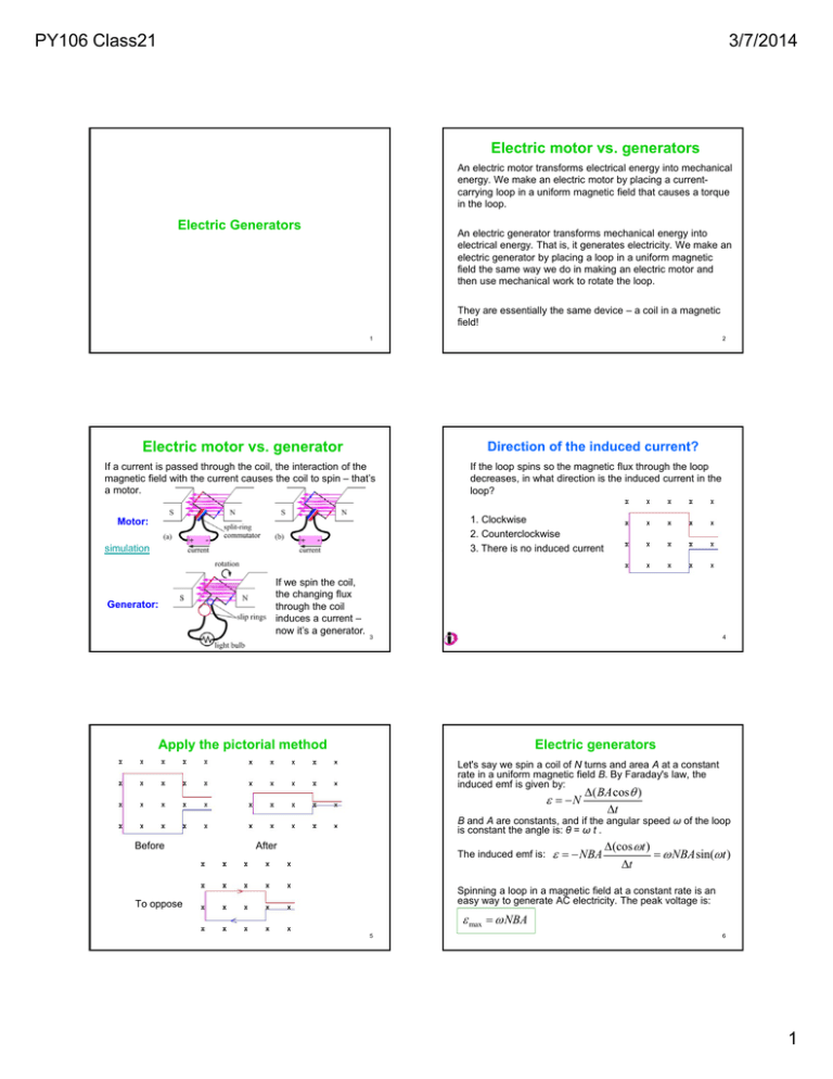
PY106 Class21 3/7/2014 Electric motor vs. generators An electric motor transforms electrical energy into mechanical energy. We make an electric motor by placing a currentcarrying loop in a uniform magnetic field that causes a torque in the loop. Electric Generators An electric generator transforms mechanical energy into electrical energy. That is, it generates electricity. We make an electric generator by placing a loop in a uniform magnetic field the same way we do in making an electric motor and then use mechanical work to rotate the loop. They are essentially the same device – a coil in a magnetic field! 1 2 Electric motor vs. generator Direction of the induced current? If a current is passed through the coil, the interaction of the magnetic field with the current causes the coil to spin – that’s a motor. If the loop spins so the magnetic flux through the loop decreases, in what direction is the induced current in the loop? 1. Clockwise 2. Counterclockwise 3. There is no induced current Motor: simulation Generator: If we spin the coil, the changing flux through the coil induces a current – now it’s a generator. 3 4 Apply the pictorial method Electric generators Let's say we spin a coil of N turns and area A at a constant rate in a uniform magnetic field B. By Faraday's law, the induced emf is given by: N ( BA cos ) t B and A are constants, and if the angular speed ω of the loop is constant the angle is: θ = ω t . Before After The induced emf is: NBA (cos t ) NBA sin(t ) t Spinning a loop in a magnetic field at a constant rate is an easy way to generate AC electricity. The peak voltage is: To oppose max NBA 5 6 1 PY106 Class21 3/7/2014 Maximum current? Maximum current At what instant is the magnitude of the current maximum? The magnitude of the current is proportional to the slope of the flux graph, so let’s draw the flux graph. 1. When the plane of the loop is perpendicular to the field (maximum area) 2. When the plane of the loop is parallel to the field (zero area) 3. Because the loop is spinning at a constant rate, the magnitude of the current is constant NBA (cos t ) NBA sin(t ) t From the graph shown at right, the slope of the flux graph (and hence the induced current) is the largest when the flux is zero. 7 8 Transformers A transformer is a device for changing the voltage of an AC signal. A transformer has two coils linked by a ferromagnetic core so the magnetic flux from one passes through the other. When the flux generated by one coil changes (as it does continually if the coil is connected to an AC power source), the flux passing through the other will change, inducing a voltage in the second coil. With AC power, the voltage induced in the second coil will also be AC. Transformers 9 Transformers DC transformer Both coils are exposed to the same changing flux, so: V p Vs t Np Ns 10 (Recall: = N(/t)) where Vp (Vs) is the voltage in the primary (secondary) coil and Np (Ns) the number of turns in the primary (secondary) coil. Energy (or, equivalently, power) has to be conserved, so: The primary coil (with Np turns) of a transformer is connected to a battery. The secondary coil (with Ns turns) is connected to a resistor. When the switch on the primary side is closed, what is the current through the resistor? 1. zero - there is no current 2. constant and equal to Np / Ns times the current in the primary 3. constant and equal to Ns / Np times the current in the primary 4. there is a brief current and then the current drops to zero V p I p Vs I s Np Ns V p Vs Is Ip 11 12 2 PY106 Class21 3/7/2014 DC transformer, II Power transmission The switch is now moved to the secondary side. When the switch is closed, what is the current through the resistor? 1. zero - there is no current 2. constant and equal to Np / Ns times the current in the primary 3. constant and equal to Ns / Np times the current in the primary 4. there is a brief current and then the current drops to zero 13 Electricity is often generated a long way from where it is used, and is transmitted long distances through power lines. Although the resistance of a short length of power line is relatively low, over a long distance the resistance can become substantial. A power line of resistance R causes a power loss of I2R ; this is wasted as heat. By reducing the current, therefore, the I2R losses can be minimized. Power companies use step-up transformers to boost the voltage to hundreds of kV (Recall: Is = Ip(Vp/Vs) so Is is reduced when the voltage is stepped up) before it is transmitted down a power line, reducing the current and minimizing the power lost in transmission lines. Step-down transformers are used at the other end, to decrease the voltage to the 120 V used in household circuits. 14 3


