ColorDMD LED Display
Installation Instructions
for Data East / SEGA
Congratulations on the purchase of a new ColorDMD display. The ColorDMD
will enhance your pinball machine by introducing color to the dot matrix
display graphics produced by the game.
Tools Required:
STEP
STEP
STEP
STEP
•
•
Phillips Screwdriver
1/4" Nut Driver
!
Be sure to turn OFF the power to the pinball machine before
installing the ColorDMD LED display.
1
Remove the original DMD from the pinball machine. Insulate
the disconnected original DMD high power cable with electrical
tape. Also disconnect the 5v power cable at CN2 on the Display
Controller Board in the backbox.
!
WARNING. Electric Shock Hazard - To protect against
accidental electric shock, DO NOT operate the game without
ensuring that the ColorDMD metal bracket is electrically grounded.
2
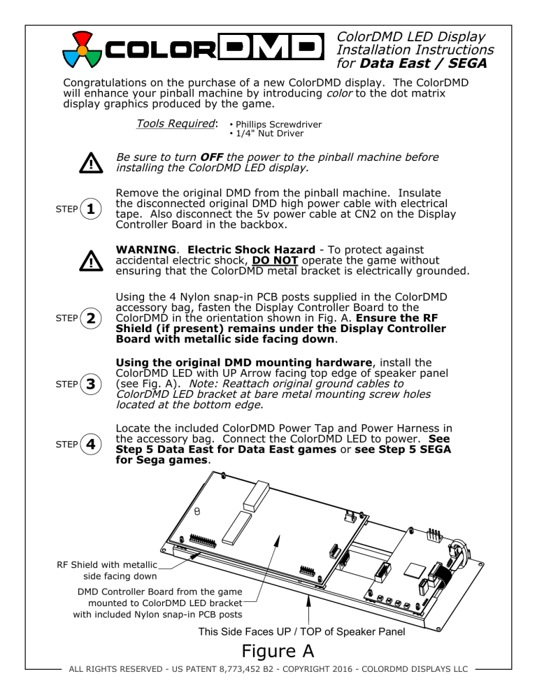
Using the 4 Nylon snap-in PCB posts supplied in the ColorDMD
accessory bag, fasten the Display Controller Board to the
ColorDMD in the orientation shown in Fig. A. Ensure the RF
Shield (if present) remains under the Display Controller
Board with metallic side facing down.
3
Using the original DMD mounting hardware, install the
ColorDMD LED with UP Arrow facing top edge of speaker panel
(see Fig. A). Note: Reattach original ground cables to
ColorDMD LED bracket at bare metal mounting screw holes
located at the bottom edge.
4
Locate the included ColorDMD Power Tap and Power Harness in
the accessory bag. Connect the ColorDMD LED to power. See
Step 5 Data East for Data East games or see Step 5 SEGA
for Sega games.
RF Shield with metallic
side facing down
DMD Controller Board from the game
mounted to ColorDMD LED bracket
with included Nylon snap-in PCB posts
This Side Faces UP / TOP of Speaker Panel
Figure A
ALL RIGHTS RESERVED - US PATENT 8,773,452 B2 - COPYRIGHT 2016 - COLORDMD DISPLAYS LLC
STEP
5
Installing the ColorDMD Power Tap (Data East).
Data East
Temporarily remove the game's 15-pin power cable connector from CN6 on the
Power Supply Circuit Board located inside the backbox (See Fig. B).
1. Attach the ColorDMD Power Harness to the ColorDMD Power Tap (see Fig. C).
2. Install the ColorDMD Power Tap to CN6 (See Fig. C). The ColorDMD Power Tap
is keyed and will only install one way.
3. Attach the game's 15-pin power cable connector to the ColorDMD Power Tap
(See Fig. C). The 15-pin power cable is keyed and will only install one way.
CN6 on Power
Supply Circuit Board
ColorDMD
Power Tap
CN6 Connector
Power Supply
Circuit Board
2
3
1
ColorDMD Power Harness
15-pin Power Cable Connector
Figure B
STEP
5
Figure C
Installing the ColorDMD Power Tap (SEGA).
SEGA
Temporarily remove the game's 15-pin power cable connector from CN6 on the
Power Supply Circuit Board located inside the backbox (See Fig. D).
1. Attach the ColorDMD Power Harness to the ColorDMD Power Tap (see Fig. E).
2. Install the ColorDMD Power Tap to CN6 (See Fig. E). The ColorDMD Power Tap
is keyed and will only install one way.
3. Attach the game's 15-pin power cable connector to the ColorDMD Power Tap
(See Fig. E). The 15-pin power cable is keyed and will only install one way.
ColorDMD Power Harness
CN6 on Power
Supply Circuit Board
1
CN6 Connector
ColorDMD
Power Tap
2
Power Supply
Circuit Board
3
15-pin Power Cable Connector
Figure D
!
Figure E
Route all power cables to ensure there is no stress on the
connections to the ColorDMD Power Tap.
ALL RIGHTS RESERVED - US PATENT 8,773,452 B2 - COPYRIGHT 2016 - COLORDMD DISPLAYS LLC
6
STEP
Locate the ColorDMD Power Harness in the accessory bag. One
end of the included ColorDMD Power Harness has a single
connector (see Fig. F). Plug this connector into the PWR header
on the ColorDMD circuit board (see Fig. G).
Connected to
ColorDMD
Power Tap
Plug into
ColorDMD
PWR
'Y' Harness:
This connector
is not used
Figure F
STEP
STEP
TIP
7
Reconnect the 5v power cable to CN2 and the 26-pin ribbon
cable to CN3 with red stripe facing the left-hand side of the
to the Display Controller Board.
8
Plug the 14-pin ribbon cable into DMD_IN on the ColorDMD
LED circuit board with the red stripe facing the top. The
other end of this cable should still be plugged into CN1 on
the Display Controller Board board with red stripe on the
right-hand side.
Coil the excess and route the ColorDMD Power Harness along
with other existing cables for a clean install.
ALL RIGHTS RESERVED - US PATENT 8,773,452 B2 - COPYRIGHT 2016 - COLORDMD DISPLAYS LLC
STEP
!
Double check for proper alignment of all cable connections.
9
While ensuring no wires get pinched, raise the speaker panel
and turn on the pinball machine.
PWR
Power Cable Connection
Bare Metal
Ground Connection
(Both Sides)
DMD_IN
Ribbon Cable
Connection
USB Port
Used For Updating
Firmware
Enter ColorDMD Menu /
Advance to Next Menu Item
Toggle Selection Up /
Confirm Menu Exit
Toggle Selection Down
Return to Previous Menu Item /
Initiate USB Download (Press for 5 Seconds)
Figure G
STEP
10
Press the right-most ColorDMD LED push-button to customize the
display settings. When finished press the Confirm push-button to
“EXIT AND SAVE”.
For additional information regarding display settings please
visit our website at www.colordmd.com.
ALL RIGHTS RESERVED - US PATENT 8,773,452 B2 - COPYRIGHT 2016 - COLORDMD DISPLAYS LLC

