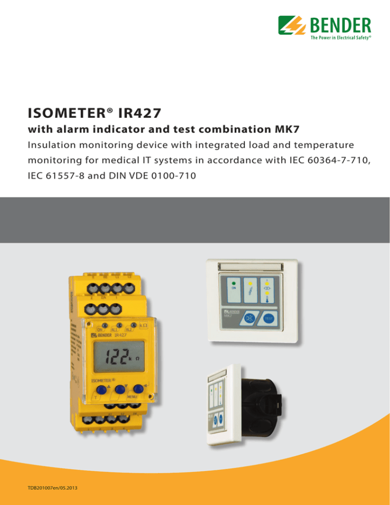
ISOMETER® IR427
advertisement

ISOMETER® IR427 with alarm indicator and test combination MK7 Insulation monitoring device with integrated load and temperature monitoring for medical IT systems in accordance with IEC 60364-7-710, IEC 61557-8 and DIN VDE 0100-710 TDB201007en/05.2013 ISOMETER® IR427 Insulation monitoring device with integrated load and temperature monitoring for medical IT systems in accordance with IEC 60364-7-710 and DIN VDE 0100-710 with alarm indicator and test combination MK7 Product description The ISOMETER® of the IR427 series is designed to monitor the insulation resistance of AC circuits (medical IT systems). At the same time, the load current and temperature of the IT system transformer can be monitored. Application Medical IT systems in accordance with IEC 60364-7-710, IEC 61557-8 and DIN VDE 0100-710. Function ISOMETER® IR427 The insulation monitoring device monitors the insulation resistance, the load current and the temperature of the IT system transformer. In addition, the connections to earth, the measuring current transformer and the temperature sensor connections are monitored. The currently measured value is indicated on the LC display. By pressing the ” “ or ” “ keys, other measured values can be displayed. Alarms are indicated on the LC display via LEDs and an additional identification. Parameters are assigned to the device via LCD or the function keys on the front of the device. Insulation monitoring The AMP measuring principle, also detects DC faults. When the value of the insulation resis­ tance falls below the set response value, the alarm relay K1 switches and the alarm LED ”AL1“ lights. When the insulation resistance exceeds the release value (response value plus hysteresis), the alarm relay returns to its initial position and the alarm LED ”AL1“ goes out. Load current and temperature monitoring Alarm indicator and test combination MK7 Device features ISOMETER® IR427 • Insulation monitoring for medical IT systems • Load and temperature monitoring for IT system transformers • Adjustable response value for insulation monitoring • Adjustable load current response value • Integrated voltage monitoring for four alarm and test combinations MK7 • Temperature monitoring with PTC thermistor or bimetal switch • Connection monitoring earth • LEDs: Power On, Alarm 1, Alarm 2 • Internal/external test button • Configurable alarm relay: N/O or N/C operation selectable • Self monitoring with automatic alarm • Compact two-module enclosure (36 mm) • Four-wire interface for four alarm indicator and test combinations MK7 Remote alarm indicator and test combination MK7 • Easy-to-clean front foil surface • Label field • Panel frame alpine white • Alarm LEDs: Power On, insulation fault overload, overtemperature • Test button, mute button • Standard flush-mounting enclosure 66 mm 2TDB201007en/05.2013 The load current is monitored via the measuring current transformer STW2; the temperature is monitored via a temperature (Bimetal) switch or a PTC Thermistor according to DIN 44081. When the response value is exceeded, the alarm LED ”AL2“ lights. The required temperature sensors are already incorporated in BENDER transformers. Alarm relays The alarm relay switches on the occurrence of an alarm or in case of voltage failure (N/C operation). The operating principle can be changed. Alarm messages LEDs “ON” Operation System fault1) Insulation fault Overcurrent Overtemperature No communication betw. IR 427+MK7 1) flashing IR427 “AL1” – flashing “AL2” – flashing – ON flashing – – – – – flashing MK7 Ins. fault Overload Overtemp. – – – flashing flashing flashing – – – – – – – – – Detailed alarm information on LCD Test function/connection monitoring The device carries out a self test when supply voltage is fed and later at hourly intervals. During the self test, the internal device functions, the connections to earth (E/KE) and the current transformer connections are monitored for interrruption and short-circuit. In the event of a fault, the alarm relay K1 switches and the LEDs ON/AL1/AL2 flash. The respective error code appears on the LC display. After eliminating the fault, the alarm relay automatically switches to its initial position. By pressing the test button, on the IR427 or on the MK7, the device functions and also the relay function will be tested. Standards The ISOMETER® of the IR427 series complies with the requirements of the device standards: IEC 60364-7-710, IEC 61557-8 and DIN VDE 0100-710. ISOMETER® IR427 Operating elements IR427 1 2 1 - Power ON LED 3 2,3 - Alarm LEDs ”AL1“, ”AL2” 4- LC display 5 - TEST button (> 2s): Call up the self test Arrow up key: parameter change to move up in the menu 6 - Arrow down key: parameter change to move down in the menu 1 2 3 ON 4 7 - MENU key (> 2s): To call up the menu system Enter key: To confirm parameter change 4 MK7 1 - Power On LED ”ON“ 2- Insulation fault LED 3- Overload LED 5 4 - Overtemperature LED 6 5 - Mute button 5 6 7 6 - Test button ”TEST“ Wiring diagram 1 - Connection to the IT system being monitored = supply voltage US via fuse 3 1 I 2 - Temperature sensor 3 - Measuring current transformer for load current monitoring 2 4 - Connection alarm indicator and test combination MK7 (max. 4 pieces) 5 5 - Line protection by a fuse in accordance with IEC 60364-4-43 (6 A fuse recommended). In case of supply (L1/L2) from an IT system, both lines have to be protected by a fuse. 4 ON ON TDB201007en/05.20133 ISOMETER® IR427 Application example Ordering information Nominal system voltage Un1) Supply voltage US AC 70…264 V, 42…460 Hz – DC – AC 70…264 V, 42…460 Hz 18…28 V – Type Art. No. IR427-2 B 7207 5300 MK7 Remote alarm indicator and test combination B 9510 0201 Device version with screw terminals on request. 1) Absolute values Accessories Suitable system components Type designation Art. No. Mounting clip for screw mounting (1 piece per device) B 9806 0008 MK-cavity-wall-box-60mm B 95100203 4TDB201007en/05.2013 Type designation Type Art. No. Measuring current transformers Temperature sensor (PTC) Mounting frame STW2 ES0107 XM420 B 942 709 B 924 186 B 990 994 ISOMETER® IR427 Technical data ISOMETER® IR427 Insulation coordination acc. to IEC 60664-1/IEC 60664-3 Rated insulation voltage Rated impulse voltage/pollution degree Protective separation (reinforced insulation) between (11, 12, 14) Voltage test acc. to IEC 61010-1 250 V 2.5 kV/3 (L1, L2, E, KE, 1, 2, 3, 4 Z, Z/k, I) 2.21 kV Supply voltage Supply voltage US Power consumption = Un ≤ 4 VA AC 70…264 V 47…63 Hz Insulation monitoring Response value Ran Relative uncertainty Hysteresis Response time tan at RF = 0.5 x Ran and Ce = 0.5 μF Permissible system leakage capacitance Ce 50…500 kΩ (50 kΩ)* ±10 % 25 % ≤5s ≤ 5 μF Measuring circuit Measuring voltage Um Measuring current Im (at RF = 0 Ω) Internal DC resistance Ri Impedance Zi at 50 Hz Permissible extraneous DC voltage Ufg ±12 V ≤ 50 μA ≥ 240 kΩ ≥ 200 kΩ ≤ DC 300 V Load current monitoring Response value, adjustable 5…50 A (7 A)* Relative uncertainty ±5% Hysteresis 4% Setting values load current measurement: Transformer 3150 VA 4000 VA 5000 VA 6300 VA 8000 VA 10000 VA Ialarm 1~ 14 A 18 A 22 A 28 A 35 A 45 A Temperature monitoring: Response value (fixed value) Release value (fixed value) PTC resistors acc. to DIN 44081 4 kΩ 1.6 kΩ max. 6 in series Displays, memory LC display multifunctional, not illuminated Measured value insulation resistance 10 kΩ…1 MΩ Operating uncertainty ± 10 %, ± 2 kΩ Measured value load current (as % of the set response value) 10 %…199 % Operating uncertainty ± 5 %, ± 0.2 A Password on, off/0…999 (off, 0)* Interface for MK7 Cable length, twisted in pairs, shielded Cable (twisted in pairs, one end of shield connected to PE) Power supply (terminals 1 and 2): Uoff Imax (max. 4 MK7) Communication (terminal 3 and 4): Interface/protocol Terminating resistor single wire > 0.5 mm² single wire, twisted > 0.5 mm² twisted in pairs, twisted > 0.5 mm² Cable (shield on one side connected to PE) ≤1m ≤ 10 m ≤ 40 m recommended: J-Y(St)Y min. 2 x 0.6 Switching elements IT system being monitored Nominal system voltage Un Nominal frequency fn Cable lengths for the connection of the measuring current transformer STW2 and the temperature sensor 200 m recommended: J-Y(St)Y min. 2 x 0.8 Number 1 changeover contact Operating principle N/C operation or N/O operation (N/C operation)* Electrical endurance, number of cycles 10000 Contact data acc. to IEC 60947-5-1 Utilisation category AC-13 AC-14 DC-12 DC-12 DC-12 Rated operational voltage 230 V 230 V 24 V 110 V 220 V Rated operational current 5 A 3 A 1 A 0.2 A 0.1 A Minimum contact rating 1 mA at AC/DC 10 V Environment/EMC EMC IEC 61326-2-4 Operating temperature -25…+55 °C Classification of climatic conditions acc. to IEC 60721: Stationary use (IEC 60721-3-3) 3K5 (except condensation and formation of ice) Transport (IEC 69721-3-2) 2K3 (except condensation and formation of ice) Long-term storage (IEC 60721-3-1) 1K4 (except condensation and formation of ice) Classification of mechanical conditions acc. to IEC 60721: Stationary use (IEC 60721-3-3) 3M4 Transport (IEC 60721-3-2) 2M2 Storage (IEC 60721-3-1) 1M3 Connection Connection type Connection properties rigid/flexible Flexible with ferrule Stripping length Opening force Test opening, diameter push-wire terminals 0.2…2.5 mm² (AWG 24…14) 0.2…1.5 mm² (AWG 24…16) 10 mm 50 N 2.1 mm Other Operating mode Position of normal use Degree of protection, internal components (DIN EN 60529) Degree of protection, terminals (DIN EN 60529) Enclosure material Flammability class Screw mounting DIN rail mounting acc. to Software version Instruction leaflet Weight continuous operation any IP30 IP20 polycarbonate UL94V-0 2 x M4 IEC 60715 D288 V1.0x TBP201007 ≤ 150 g ( )* = Factory setting DC 24 V 80 mA RS-485/proprietary, no BMS 120 (0.25 W), internal, switchable TDB201007en/05.20135 Technical data MK7 Dimension diagram IR427 Insulation coordination acc. to IEC 60664-1/IEC 60664-3 Dimensions are given in mm Rated insulation voltage Rated impulse voltage/pollution degree 50 V 500 V/3 Screw fixing Open the front plate cover in di- Note: Pull out the mounting clip for screw mounting. rection of arrow! Supply voltage Supply voltage US Power consumption DC 18…28 V 0.5 VA Environment/EMC EMC IEC 61326 Operating temperature -10…+55 °C Classification of climatic conditions acc. to IEC 60721: Stationary use (IEC 60721-3-3) 3K5 (except condensation and formation of ice) Transport (IEC 69721-3-2) 2K3 (except condensation and formation of ice) Long-term storage (IEC 60721-3-1) 1K4 (except condensation and formation of ice) Classification of mechanical conditions acc. to IEC 60721: Stationary use (IEC 60721-3-3) 3M4 Transport (IEC 60721-3-2) 2M2 Storage (IEC 60721-3-1) 1M3 Connection Connection Connection properties rigid/flexible Flexible with ferrule Stripping length screw-type terminals 0.2…2.5 mm² (AWG 24…14) 0.2…1.5 mm² (AWG 24…16) 8 mm Dimension diagram MK7 and flush-mounting enclosure Dimensions are given in mm 10 Flush-mounting box Ø 66 Drilling hole Ø 70 Other Bender GmbH & Co. KG P.O. Box 1161 • 35301 Grünberg • Germany Londorfer Straße 65 • 35305 Grünberg • Germany Tel.: +49 6401 807-0 • Fax: +49 6401 807-259 E-Mail: info@bender-de.com • www.bender-de.com 80 ON 50 50 80 60 Distance screw mounting BENDER Group Subject to change! – TDB201007en / 05.2013 / Schw / © Bender GmbH & Co. KG, Germany Operating mode continuous operation Position of normal use any Degree of protection, internal components (IEC 60529) IP30 Degree of protection, terminals (IEC 60529) IP20 Front plate colour alpine white Flush-mounting enclosure, diameter (included in the scope of delivery) 66 mm Weight (including mounting frame) ≤ 80 g


