EMERGENCY LIGHTING UNITS INSTRUCTIONS - Dual-Lite
advertisement
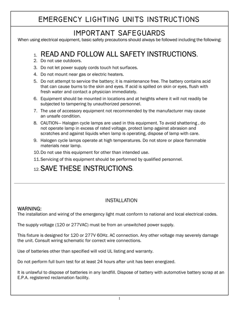
EMERGENCY LIGHTING UNITS INSTRUCTIONS IMPORTANT SAFEGUARDS When using electrical equipment, basic safety precautions should always be followed including the following: 1. 2. 3. 4. 5. READ AND FOLLOW ALL SAFETY INSTRUCTIONS. Do not use outdoors. Do not let power supply cords touch hot surfaces. Do not mount near gas or electric heaters. Do not attempt to service the battery; it is maintenance free. The battery contains acid that can cause burns to the skin and eyes. If acid is spilled on skin or eyes, flush with fresh water and contact a physician immediately. 6. Equipment should be mounted in locations and at heights where it will not readily be subjected to tampering by unauthorized personnel. 7. The use of accessory equipment not recommended by the manufacturer may cause an unsafe condition. 8. CAUTION— Halogen cycle lamps are used in this equipment. To avoid shattering , do not operate lamp in excess of rated voltage, protect lamp against abrasion and scratches and against liquids when lamp is operating, dispose of lamp with care. 9. Halogen cycle lamps operate at high temperatures. Do not store or place flammable materials near lamp. 10.Do not use this equipment for other than intended use. 11.Servicing of this equipment should be performed by qualified personnel. 12. SAVE THESE INSTRUCTIONS. INSTALLATION WARNING: The installation and wiring of the emergency light must conform to national and local electrical codes. The supply voltage (120 or 277VAC) must be from an unswitched power supply. This fixture is designed for 120 or 277V 60Hz. AC connection. Any other voltage may severely damage the unit. Consult wiring schematic for correct wire connections. Use of batteries other than specified will void UL listing and warranty. Do not perform full burn test for at least 24 hours after unit has been energized. It is unlawful to dispose of batteries in any landfill. Dispose of battery with automotive battery scrap at an E.P.A. registered reclamation facility. 1 INSTALLATION/SERVICE INSTRUCTIONS 1. Disconnect power to the unit before installing or servicing. 2. Carefully remove unit from carton. Recessed Can Outlet Box Place Gimbal/Lamp assembly Assembly aside. Assemble Mounting bars to Recessed can assembly and install in ceiling .( See below “Installing Fixture in Ceiling”) 3. Run wires to Outlet Box using knockouts leaving 6 - 8 inches extending through Outlet Box Door. NOTE: circuit must be Red Battery Lead from a 24 hour, unswitched Lamp Wire Harness 120V or 277V line. 4. Remove AC wire harness in Outlet Box and connect stripped ends to Torsion Springs AC power as follows: connect Indicator Light black lead for 120 volt connection, & Test Button or connect orange lead for 277 volt connection. NOTE: insulate the unused black or orange Gimbal/Lamp Asssembly lead. Connect green (ground) lead and white (neutral) lead to AC power. Then replace Outlet Box Door. 5. Connect Red Battery Lead by using two piece connector . 6. Connect lamp wire harness to mating connector . Install Gimbal/Lamp Assembly in Recessed Can. Carefully Compress Torsion Springs and release in spring retainer. Once the two torsion spring assemblies are in place push the Gimbal assembly into the recessed can. 7. The Indicator Light will be lit when AC circuit is energized. To test the unit, simulate a power outage by pressing the Test Button. Indicator Light will turn off and emergency light will turn on. INSTALLING FIXTURE IN CEILING Joist type ceilings (Fig. 1): Extend bar hangers to fit between joists. Position fixture temporarily by hammering nail-in tabs into joists, then secure permanently with nails. Hangers should be level with bottom of joists. Suspended (T-bar) Ceilings (Fig.2): Extend bar hangers one inch past T-bars, then rest fixture on T-bars. Properly secure the fixture to ceiling joists with wire (not included). Nail-in Tabs Fig. 1 Fig. 2 Be sure that all related electrical power is disconnected before installing or maintaining the fixture. Failure to do so may result in injury or death 2 51070 rga 05/03 WARNING
