WAT03 BREEAM PIR WATER SUPPLY ISOLATOR
TECHNICAL SPECIFICATION
Working Principles of the Waterguard PIR System
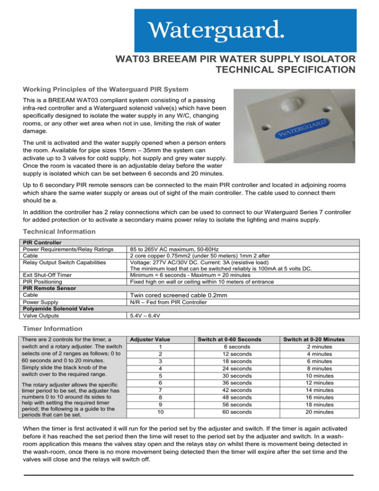
This is a BREEAM WAT03 compliant system consisting of a passing
infra-red controller and a Waterguard solenoid valve(s) which have been
specifically designed to isolate the water supply in any W/C, changing
rooms, or any other wet area when not in use, limiting the risk of water
damage.
The unit is activated and the water supply opened when a person enters
the room. Available for pipe sizes 15mm – 35mm the system can
activate up to 3 valves for cold supply, hot supply and grey water supply.
Once the room is vacated there is an adjustable delay before the water
supply is isolated which can be set between 6 seconds and 20 minutes.
Up to 6 secondary PIR remote sensors can be connected to the main PIR controller and located in adjoining rooms
which share the same water supply or areas out of sight of the main controller. The cable used to connect them
should be a.
In addition the controller has 2 relay connections which can be used to connect to our Waterguard Series 7 controller
for added protection or to activate a secondary mains power relay to isolate the lighting and mains supply.
Technical Information
PIR Controller
Power Requirements/Relay Ratings
Cable
Relay Output Switch Capabilities
Exit Shut-Off Timer
PIR Positioning
PIR Remote Sensor
Cable
Power Supply
Polyamide Solenoid Valve
Valve Outputs
85 to 265V AC maximum, 50-60Hz
2 core copper 0.75mm2 (under 50 meters) 1mm 2 after
Voltage: 277V AC/30V DC. Current: 3A (resistive load)
The minimum load that can be switched reliably is 100mA at 5 volts DC.
Minimum = 6 seconds - Maximum = 20 minutes
Fixed high on wall or ceiling within 10 meters of entrance
Twin cored screened cable 0.2mm
N/R – Fed from PIR Controller
5.4V – 6.4V
Timer Information
There are 2 controls for the timer, a
switch and a rotary adjuster. The switch
selects one of 2 ranges as follows; 0 to
60 seconds and 0 to 20 minutes.
Simply slide the black knob of the
switch over to the required range.
The rotary adjuster allows the specific
timer period to be set, the adjuster has
numbers 0 to 10 around its sides to
help with setting the required timer
period; the following is a guide to the
periods that can be set.
Adjuster Value
1
2
3
4
5
6
7
8
9
10
Switch at 0-60 Seconds
6 seconds
12 seconds
18 seconds
24 seconds
30 seconds
36 seconds
42 seconds
48 seconds
56 seconds
60 seconds
Switch at 0-20 Minutes
2 minutes
4 minutes
6 minutes
8 minutes
10 minutes
12 minutes
14 minutes
16 minutes
18 minutes
20 minutes
When the timer is first activated it will run for the period set by the adjuster and switch. If the timer is again activated
before it has reached the set period then the time will reset to the period set by the adjuster and switch. In a washroom application this means the valves stay open and the relays stay on whilst there is movement being detected in
the wash-room, once there is no more movement being detected then the timer will expire after the set time and the
valves will close and the relays will switch off.
Installing the PIR Range
The range of PIR sensors are currently available in ceiling surface mounted and wall mounted configurations (please
enquire for any other). The internal PIR sensor has a range of 10 Metres. The device must be located so the sensor
will detect movement within its field of view.
If the PIR controller cannot be located where all movement will be within its field
of view then additional PIR remote sensors may be used.
This
being
diagram shows a controller and remote
used to provide full coverage of an L
shaped room.
Valve Driver Output
There are 3 valve driver outputs; all outputs are designed to drive bipolar valves, e.g. a valve that will open with a
pulse of electricity in one direction and close with a pulse of electricity in the opposite direction.
The driver outputs are designed to drive valves with the following rating- Valve voltage: 6 to 9 Volts- Valve peak
current: 1.2 Amp.
When the timer is activated all 3 valve drivers will produce a pulse of electricity with contact A as positive. When the
timer reaches its set time period then all 3 valve drivers will produce a pulse of electricity with contact B as positive.
Included as standard with our Waterguard Wash Room PIR systems, the Waterguard range of polyamide valves are
all WRAS approved, highly efficient, durable and reliable. Available in sizes 15mm to 35mm these; 5.4V – 6.4V.
Classification
Hydraulic Connections
Type
Inlet
Single
Geometry
Outlet
180 C
Working Specifications
Physical Specifications
Working Pressure
Valve Body
0.5 / 10 bar
Room Temperature
Diaphragm and Gaskets
0 / 60 C
Fluid Temperature
Core
60 C
Duty Cycle
Spring
ED 100%
Flow Direction
Assembly
Unidirectional
Nominal Diameter
Coil
DN 15-54mm
Control
NC, NO, Latching
Installation
In all positions, manual override by solenoid coils rotation
Electrical Connections
Electric Connect 1
Male Faston 6.3 x 0.8 mm – IP X0
Electric Connect 2
Unipolar Cables max 300 mm – IP 55
Electric Connect 3
Bipolar Cables max 5000 mm – IP 55
BSP Female Thread
BSP Female Thread
Polyamide 30% fibre glass
NBR (buna)
Stainless Steel
Stainless Steel
With screws for inspection
Watertight – C.E.I IP 55
IMPORTANT: All information provided, including installations is held to be reliable. Clients should however independently evaluate the suitability of each system to their
individual application. Waterguard Services Limited, registered address 22 Oakwell Business Centre, Oakwell View, Barnsley, S71 1HX makes no warranty as to the
accuracy of this information, and retracts any liability regarding its use. The only responsibilities of Waterguard Services Limited are those in the Waterguard Services
Limited Standard Terms and Conditions of Sale for this product, and in no case will Waterguard Services Limited be liable for any incidental, indirect or consequential
damages arising from the sale, resale, use or misuse of the product. Due to continual development specifications are subject to regular change without notice.
©2016 Waterguard Services Limited, All Rights Reserved.

