AUTOMATIC TRANSFER SWITCH
CAT® POWER BREAKER
BYPASS ISOLATION
OPEN / CLOSED TRANSITION
AUTOMATIC TRANSFER
SWITCH
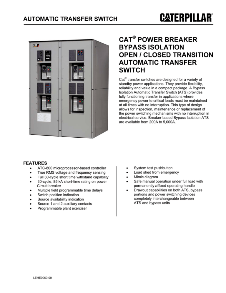
Cat® transfer switches are designed for a variety of
standby power applications. They provide flexibility,
reliability and value in a compact package. A Bypass
Isolation Automatic Transfer Switch (ATS) provides
fully functioning transfer in applications where
emergency power to critical loads must be maintained
at all times with no interruption. This type of design
allows for inspection, maintenance or replacement of
the power switching mechanisms with no interruption in
electrical service. Breaker-based Bypass Isolation ATS
are available from 200A to 5,000A.
FEATURES
•
•
•
•
•
•
•
•
•
ATC-800 microprocessor-based controller
True RMS voltage and frequency sensing
Full 30-cycle short time withstand capability
30-cycle, 85 kA short-time rating on power
Circuit breaker
Multiple field programmable time delays
Switch position indication
Source availability indication
Source 1 and 2 auxiliary contacts
Programmable plant exerciser
LEHE0060-00
•
•
•
•
•
System test pushbutton
Load shed from emergency
Mimic diagram
Safe manual operation under full load with
permanently affixed operating handle
Drawout capabilities on both ATS, bypass
portions and power switching devices
completely interchangeable between
ATS and bypass units
AUTOMATIC TRANSFER SWITCH
OPTIONS
• Integrated service entrance
• Open or Closed Transition
• Integral overcurrent protection
• 2- or 4-position test switch
• Multi meter options available
• Selectable Automatic or Non-Automatic operation
• Space heaters
• Load sequencing contacts
• Surge suppression
• Remote communications
• Seismic Zone 4 Qualified (BOCA, CBC, IBC, UBC)
• Field selectable, multi ratio, control voltage transformer
50/60 Hz
OPTIONAL DELAYED TRANSITION INCLUDES:
• Time Delay Neutral
• In-Phase Transition
• Pre-Transfer Signal with 1 N.O. and 1 N.C. contacts
RATINGS
• 200-5000A 2-, 3-, 4-pole
• 120 – 600 Vac 50/60 Hz
• 100% rated Short
• Time Withstand – 85,000 for 30 cycles / 100 kAIC
at 600V 3 cycles
• UL 1008 listed
• CSA C22.2 No. 178 certified
• UL 1008 listed up to 3200A, 4000A, and 5000A UL 891 listed
CONTROLS AND WIRING
All control relays and industrial-grade relays are
totally encapsulated to minimize exposure to dust and dirt.
Lugs are 90ºC rated and all control wire is #16 AWG,
type XLPE with a 125°C temperature rating.
ENCLOSURE
Durable powder-coated steel NEMA 1, 3R, or 12 enclosures
with three door hinges to ensure proper support of the door
and door mounted devices. The hinges have removable
hinge pins to facilitate door removal for easy wall mounting
or service and are supplied with pad-lockable latches.
LEHE0060-00
2
AUTOMATIC TRANSFER SWITCH
TESTING STANDARDS
UL 991 UL standards for safety tests for safety-related
IEC 1000-5 Surge withstand tests
controls employing solid-state devices
NEMA® ICS 109.21 Impulse withstand test
UL 1008 Dielectric test (endurance, withstand, etc.)
CSA® conformance C22.2 No. 178-1978 (reaffirmed 1992)
IEEE® 472 (ANSI C37.90A) Ringing wave
UL 869A Reference Std for Service Equipment
immunity/voltage surge test
UL 50/508 Enclosures
EN55022 (CISPR11): Conducted and radiated emissions
NEMA ICS 1 General standards for industrial control system
EN61000-4-2 Class B Level 4 ESD immunity test
NEMA ICS 2 Standards for industrial control devices,
EN61000-4-3 (ENV50140) radiated RF,
controllers, and assemblies
electromagnetic field immunity test
NEMA ICS 6 Enclosures for industrial controls and systems
EN61000-4-4 Electrical fast transient/burst immunity test
NEMA ICS 10-1993 AC automatic transfer switches
EN61000-4-5 IEEE C62.41: Surge immunity test
ANSI C33.76 Enclosures
EN61000-4-6 (ENV50141) Conducted immunity test
NEC® 517, 700, 701, and 702 National Electrical Code
EN61000-4-11 Voltage dips and interruption immunity
NFPA® 70 National Fire Protection Agency
FCC Part 15 Conducted/radiated emissions (Class A)
NFPA 99 Health care facilities
CISPR 11 Conducted/radiated emissions (Class A)
NFPA 101 Life safety code
IEC 1000-2 Electrostatic discharge test
NFPA 110 Emergency and standby power systems
IEC 1000-3 Radiated susceptibility tests
EGSA 100S Standard for transfer switches
IEC 1000-4 Fast transient tests
CSA C22.2 No. 178-1978 Canadian Standards Association
UL 1008 WITHSTAND AND CLOSE-ON RATINGS (kA)
Rating When Used with:
Upstream Circuit
Upstream Fuse
Breaker
Ampere
Rating
3-Cycle
600 V (kA)
30-Cycle
600 V (kA)
800
100
85
1000
100
85
1200
100
85
1600
100
85
2000
100
85
2500
100
85
3200
100
85
4000
100
85
5000
100
85
LEHE0060-00
3
AUTOMATIC TRANSFER SWITCH
BYPASS ISOLATION TRANSFER SWITCH 200 – 5000A DIMENSIONS*
Enclosure
Number of
Ampere Rating
Poles
Height
Standard Terminals
Width
Depth
Load Side,
Normal, and
Standby Source
Neutral
Connection
Shipping
Weight Lbs.
(kg)
64 (1626)
60 (1524)
(6) 3/0 - 750
(24) 4/0 - 500
3100 (1409)
kcmil
3100 (1409)
NEMA 1 Enclosed Drawout Transfer Switch
200-2000@ 480V
200-2000@ 600V
2500-3200@480V
2500-3200@600V
4000-5000A
2
90 (2286)
3
90 (2286)
64 (1626)
60 (1524)
kcmil
4
90 (2286)
64 (1626)
60 (1524)
Bottom Entry
2
90 (2286)
64 (1626)
60 (1524)
(6) 3/0 - 750
(24) 4/0 - 500
3100 (1409)
3
90 (2286)
64 (1626)
60 (1524)
kcmil
kcmil
3100 (1409)
4
90 (2286)
64 (1626)
60 (1524)
Bottom Entry
2
90 (2286)
64 (1626)
60 (1524)
(9) 3/0 - 750
(36) 4/0 - 500
4700 (2136)
3
90 (2286)
64 (1626)
60 (1524)
kcmil
kcmil
4700 (2136)
3700 (1682)
3700 (1682)
4
90 (2286)
64 (1626)
60 (1524)
Bottom Entry
2
90 (2286)
64 (1626)
60 (1524)
(9) 3/0 - 750
(36) 4/0 - 500
4700 (2136)
5500 (2500)
3
90 (2286)
64 (1626)
60 (1524)
kcmil
kcmil
4700 (2136)
4
90 (2286)
64 (1626)
60 (1524)
Bottom Entry
5500 (2500)
2
Consult Factory
3
4
NEMA 3R Enclosed Drawout Transfer Switch
200-2000A@480V
200-2000A@600V
2500-3200A@480
2500-3200A@600
4000-5000A
2
90 (2286)
64 (1626)
75 (1905)
(6) 3/0 - 750
(24) 4/0 - 500
4100 (1864)
3
90 (2286)
64 (1626)
4
90 (2286)
64 (1626)
75 (1905)
kcmil
kcmil
4100 (1864)
75 (1905)
Bottom Entry
2
90 (2286)
64 (1626)
75 (1905)
(6) 3/0 - 750
(24) 4/0 - 500
4100 (1864)
3
90 (2286)
64 (1626)
75 (1905)
kcmil
kcmil
4100 (1864)
4700 (2136)
4
90 (2286)
64 (1626)
75 (1905)
Bottom Entry
2
90 (2286)
64 (1626)
75 (1905)
(9) 3/0 - 750
(36) 4/0 - 500
5700 (2591)
4700 (2136)
3
90 (2286)
64 (1626)
75 (1905)
kcmil
kcmil
5700 (2591)
4
90 (2286)
64 (1626)
75 (1905)
Bottom Entry
2
90 (2286)
64 (1626)
75 (1905)
(9) 3/0 - 750
(36) 4/0 - 500
5700 (2591)
6500 (2955)
3
90 (2286)
64 (1626)
75 (1905)
kcmil
kcmil
5700 (2591)
4
90 (2286)
64 (1626)
75 (1905)
Bottom Entry
6500 (2955)
2
3
Consult Factory
4
Dimensions in Inches (mm) & Approximate Shipping lbs (kg)
* Add 6" to the width and 3" to the depth for seismic brackets where required
Information contained in this publication may be considered confidential. Discretion is recommended when distributing.
Materials and specifications are subject to change without notice.
CAT, CATERPILLAR, their respective logos, “Caterpillar Yellow”, the “Power Edge” trade dress, as well as corporate
and product identity used herein, are trademarks of Caterpillar and may not be used without permission.
www.Cat-ElectricPower.com
LEHE0060-00
LEHE0060-00 (10-09)
4
©2009 Caterpillar
All Rights Reserved.
Printed in U.S.A.

