Auber P210 Installation Guide
Fuel/oil Pressure Transducer Installation Guide
A. Installation of Auber P210 oil/fuel transducer
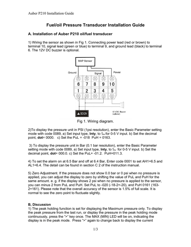
1) Wiring the sensor as shown in Fig 1. Connecting power lead (red or brown) to
terminal 10, signal lead (green or blue) to terminal 9, and ground lead (black) to terminal
6. The 12V DC buzzer is optional.
Fig 1. Wiring diagram.
2)To display the pressure unit in PSI (1psi resolution), enter the Basic Parameter setting
mode with code 0089, a) Set input type, Inty, to 5vfor 0-5 V input. b) Set the decimal
point, dot= 0000. c) Set the PuL = -018 PuH = 0163.
3) To display the pressure unit in Bar (0.1 bar resolution), enter the Basic Parameter
setting mode with code 0089, a) Set input type, Inty, to 5v for 0-5 V input. b) Set the
decimal point, dot= 000.0. c) Set the PuL= -01.2. PuH=011.3.
4) To set the alarm on at 6.5 Bar and off at 6.4 Bar, Enter code 0001 to set AH1=6.5 and
AL1=6.4. The detail can be found in section C 2 of the instruction manual.
5) Zero Adjustment. If the pressure does not show 0.0 bar or 0 psi when no pressure is
applied, you can adjust the display to zero by shifting the value of PuL and PuH for the
same amount. e. g. if the display shows 2 psi when no pressure is applied to the sensor,
you can minus 2 from PuL and PuH. Set PuL to -020 (-18-2=-20), and PuH 0161 (1632=161). Please note that the overall accuracy of the sensor is 1.5% of full scale. It is
normal to see the zero point to fluctuate slightly.
B, Discussion
1) The peak holding function is set for displaying the Maximum pressure only. To display
the peak pressure from the last run, or display the pressure in the peak holding mode
continuously, press the “>” key once. The MAX (MIN) LED will be on, indicating the
display is in the peak mode. Press “>” again to change back to display the current
1/3
Auber P210 Installation Guide
pressure. Press and hold “Λ” for 3 second will reset the memory. Three additional peak
parameters are turned off. They are, the time that the maximum pressure was recorded,
the minimum pressure and its recording time. If you want see them, use code 0037 to
turn on these functions. The detail can be found in section C3 of the instruction manual.
2) This instruction is for the SYL-1813 that has the 5 V power supply (for the pressure
sensor) enabled at terminal 10. If you have an older model, (SYL-1812), you need to get
the 5 V out to terminal 10. Please ask factory for instruction on how to do it.
3) If you want the meter to display a pressure unit that is not Bar or PSI, or if you have a
pressure sensor (sender, transducer or transmitter) that has different output specification,
you need to find the value of PuL and PuH. Appendix 1 shows how the Auber P210
sensor parameter is determined. If you need help, please email us the specification of
your sensor to info@auberins.com
C. Appendix 1,
Example, how to determine the set up parameters for Auber P210 transducer.
For a pressure sensor that is powered by 5 V DC, the linear range of the output signal
will be above 0V and less than 5 V due to the nature of mechanics and electronics.
Auber P210 published data. 0 bar = 0.5V, 10 bar =4.5 V. What these data tell us is that
the sensor has a linear output between 0.5 and 4.5 V when the input signal is between 0
and 10 Bar, In other words, within this range, the relationship between pressure and
output voltage can be represented by
V = a x P + b (1)
Where P is the pressure, V is the voltage. a, is the slop, b is the intersection at zero
pressure,
Because the meter is set for 0-5V linear input, we need to find out what is the pressure
when we extend the equation (1) from 0.5-4.5V to the 0 and 5 V.
Calculating slop a and intersection b
a= (4.5-0.5)/(10-0) = 0.4
b = 0.5
So, V = 0.4P +0.5, or P = (V -0.5)/0.4
Therefore, at 0 V, P = -1.25; at 5 V, P = 11.25.
To display pressure in Bar,
Set dot to 000.0, PuL=-1.2, PuH=11.3
To display the pressure with PSI units instead of Bar, multiply the number by 14.5
(1bar=14.503PSI)
Set dot to 0000, PuL=-18, PuH=163.
2/3
Auber P210 Installation Guide
Auber Instruments Inc.
5755 North Point Parkway, Suite 99,
Alpharetta, GA 30022
www.auberins.com
Email: info@auberins.com
Tel: 770-569-8420
Copyright 2007-2015, Auber Instruments All Rights Reserved.
No part of this manual shall be copied, reproduced, or transmitted in any way without the
prior, written consent of Auber Instruments. Auber Instruments retains the exclusive
rights to all information included in this document.
3/3


