Series 3100/3200 Compact High Pressure OEM Pressure Transmitter
advertisement

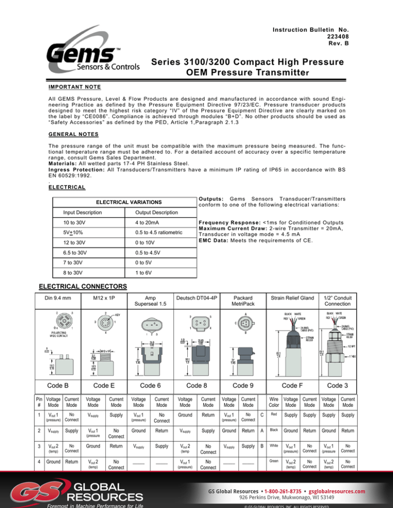
Instruction Bulletin No. 223408 Rev. B Series 3100/3200 Compact High Pressure OEM Pressure Transmitte r IMPORTANT NOTE All GEMS Pressure, Level & Flow Products are designed and manufactured in accordance with sound Engi neering Practice as defined by the Pressure Equipment Directive 97/23/EC. Pressure transducer products designed to meet the highest risk category “IV” of the Pressure Equipment Directive are clearly marked on the label by “CE0086”. Compliance is achieved through modules “B+D”. No other products should be used as “Safety Accessories” as defined by the PED, Article 1,Paragraph 2.1.3 GENERAL NOTES The pressure range of the unit must be compatible with the maximum pressure being measured. The functional temperature range must be adhered to. For a detailed account of accuracy over a specific temperature range, consult Gems Sales Department. Materials: All wetted parts 17-4 PH Stainless Steel. Ingress Protection: All Transducers/Transmitters have a minimum IP rating of IP65 in accordance with BS EN 60529:1992. . ELECTRICAL Outputs: Gems Sensors Transducer/Transmitters conform to one of the following electrical variations: ELECTRICAL VARIATIONS Input Description Output Description 10 to 30V 4 to 20mA 5V+10% 0.5 to 4.5 ratiometric 12 to 30V 0 to 10V 6.5 to 30V 0.5 to 4.5V 7 to 30V 0 to 5V 8 to 30V 1 to 6V Frequency Response: <1ms for Conditioned Outputs Maximum Current Draw : 2-wire Transmitter = 20mA, Transducer in voltage mode = 4.5 mA EMC Data: Meets the requirements of CE. ELECTRICAL CONNECTORS Din 9.4 mm M12 x 1P Amp Superseal 1.5 Deutsch DT04-4P Packard MetriPack Strain Relief Gland 1/2” Conduit Connection Code B Code E Code 6 Code 8 Code 9 Code F Code 3 Pin Voltage Current # Mode Mode 1 2 3 Vout 1 (pressure) No Connect Vsupply Supply Vout 2 (temp) 4 No Connect Ground Return Voltage Mode Current Mode Vsupply Supply Voltage Mode Current Mode Voltage Mode Current Mode Vout 1 No Connect Ground Return (pressure) Voltage Current Mode Mode Wire Voltage Current Voltage Current Color Mode Mode Mode Mode No Connect C Red Supply Supply Supply Supply (pressure) Ground Return Ground Return Vout 1 No Connect Vout 1 (pressure No Connect Vout 1 No Connect Ground Return Vsupply Supply Ground Return A Black (pressure Ground Return Vsupply Supply Vout 2 No Connect Vsupply Supply B White No Connect _____ Vout 1 (temp Vout 2 (temp) No Connect _____ _____ Vout 1 (pressure) (pressure) _____ Green Vout 2 (temp) No Connect Vout 2 (temp) No Connect Wiring Diagrams Current Output Mode (Load Resistor Range) Minimum Resistor Value = 50 + (+V-24) for +V>24V Maximum Resistor Value = 50 + (+V-8) for +V >8V MECHANICAL Pressure Ranges: See Table below Pressure Range PSI (Bar) Proof Pressure (x Full Scale) 3100 50-300 (3.5-25) Burst Pressure (x Full Scale) 3200 3100 3.00 x FS 40 x FS 500-1,500 (40-100) 20 x FS 3.00 x FS 2,000-6,000 (160-400) 7,500-9,000 (600) 15,000 (1,000) 30,000 (2,200) 10 x FS 10 x FS 2.00 x FS 4 x FS 10,000 (700) 25,000 (1,800) 3200 >60,000 PSI (4,000 bar) 2.50 x FS 1.40 x FS 1.8 x FS — 1.5 x FS — NPTF (Dryseal) & Standard Tapered Threads: ‘Dryseal’ Pipe threads are designed to seal pressure tight joints without the need of compounds. To accomplish the seal, the root of both internal and external threads are truncated slightly more than the crests, i.e. roots have wider flats than crests. Therefore, metal-to-metal contact occurs when wrenching and crushing the sharper crests of the mating thread, thus creating the pressure tight joint and preventing spiral leakage. However, where functionally not objectionable, Gems Sensors recommend the use of an Anaerobic sealing compound to ensure an absolute pressure tight seal and minimise thread galling. Standard taper threads require the use of a sealing compound and are not interchangeable with ‘R’ designated threads. Installation: Transducers and Transmitters can be installed by either spanner or deep socket. Sizes 22 A/F and 27 A/E. The tightening torque depends upon the material and the sealing mechanism. The tightening torque should not exceed 30Nm in any case. Vibration: 40g peak to peak sinusoidal (Random Vibration: 20 to 1000 Hz @ approx. 40G peak per MIL-STD-810E) Operation: Having installed the transducers as instructed, they are ready for use. Before applying power, check that the correct polarity and excitation levels are being applied. Maintenance: Routine Inspection not required except for periodic inspection of the cable and connector to ensure that these are neither damaged nor softened by incompatible liquid. Warranty: We guarantee this instrument against faulty workmanship and material for a period of one year from date of delivery. The Company undertake to repair, free of charge, ex-works any instrument found to be defective within the specified period providing the instrument has been used within the specification in accordance with these instructions and has not been misused in any way. Detailed notice of such defects and satisfactory proof thereof must be given to the Company immediately after the discovery and the goods are to be returned free of charge to the Company, carefully packed and accompanied by a detailed failure report. See "Return Policy". Gems Sensors & Controls 1 Cowles Road, Plainville, CT 06062 Toll-Free: 1-800-378-1600

