860484955
Issue 5, April 2014
www.commscope.com
SYSTIMAX 360™ 360G2 Modular Internal Sliding
– Combination Shelf Instructions
General
™
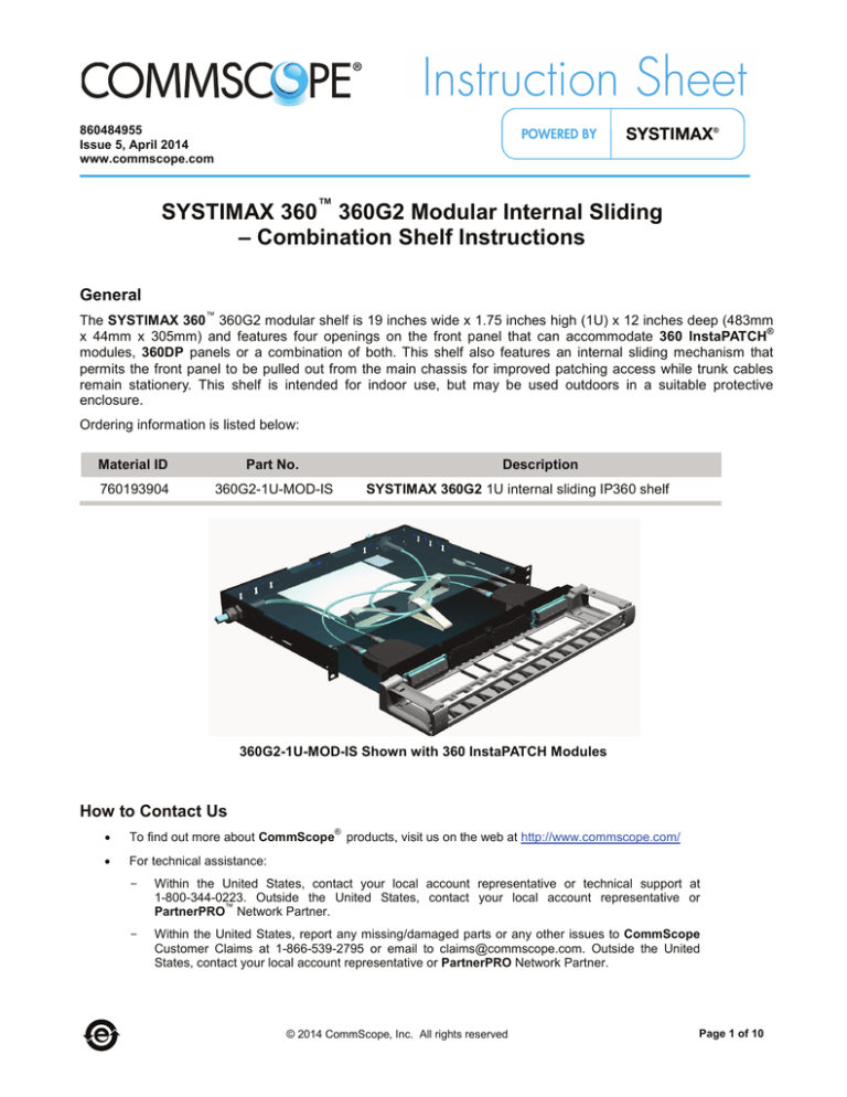
The SYSTIMAX 360 360G2 modular shelf is 19 inches wide x 1.75 inches high (1U) x 12 inches deep (483mm
®
x 44mm x 305mm) and features four openings on the front panel that can accommodate 360 InstaPATCH
modules, 360DP panels or a combination of both. This shelf also features an internal sliding mechanism that
permits the front panel to be pulled out from the main chassis for improved patching access while trunk cables
remain stationery. This shelf is intended for indoor use, but may be used outdoors in a suitable protective
enclosure.
Ordering information is listed below:
Material ID
Part No.
760193904
360G2-1U-MOD-IS
Description
SYSTIMAX 360G2 1U internal sliding IP360 shelf
360G2-1U-MOD-IS Shown with 360 InstaPATCH Modules
How to Contact Us
®
•
To find out more about CommScope products, visit us on the web at http://www.commscope.com/
•
For technical assistance:
-
Within the United States, contact your local account representative or technical support at
1-800-344-0223. Outside the United States, contact your local account representative or
™
PartnerPRO Network Partner.
-
Within the United States, report any missing/damaged parts or any other issues to CommScope
Customer Claims at 1-866-539-2795 or email to claims@commscope.com. Outside the United
States, contact your local account representative or PartnerPRO Network Partner.
© 2014 CommScope, Inc. All rights reserved
Page 1 of 10
www.commscope.com
860484955
Instruction Sheet
Tools Required
•
•
•
Phillips-head screwdriver
Flat-blade screwdriver
Adjustable wrench or open-end wrench
Available Accessories
Ordering information for available accessories is listed below.
Material ID
Part No.
Description
760148502
360-LP-STACK-SPT
Stackable fusion splice tray kit
760032102
MODG2-BLANK
G2 Modular blank panel bezel (package of 4)
760032110
MODG2-MGS
G2 Modular MGS bezel (package of 4)
760039875
G2-SRF
Liquid-tight cable fitting kit for small-diameter cables
760039883
G2-23BRKT
Frame mounting bracket kit for 23” frames and ETSI frames
760056549
G2G2-Fiber Drum Kit
Includes 2 fiber drums and mounting hardware
760055921
G2 Cover Metal
Metal (Security) top cover for shelf
760107482
DP360-BLANK
360 InstaPATCH blank panel (pkg of 4)
760107490
DP360-2MPO
360 InstaPATCH 2 MPO adapter panel
760107508
DP360-4MPO
360 InstaPATCH 4 MPO adapter panel
760107516
DP360-6MPO
360 InstaPATCH 6 MPO adapter panel
760107524
DP360-8MPO
360 InstaPATCH 8 MPO adapter panel
760105676
360 G2-1U-FLK
360 G2 1U trough flip label kit
760105684
360 G2-2U-FLK
360 G2 2U trough flip label kit
Parts List
Verify parts against the parts list below:
Quantity
Description
1
1
1
Shelf assembly
Trough assembly (includes door assembly)
Polycarbonate top cover
1
4
1
3
1
12-24 x ¼ “ screws
M6 x 12 mm screws for ETSI rack mounting
Flip label holder
Label hangers
Instruction sheet
! Important Safety Cautions
•
Disconnected optical components may emit invisible optical radiation that can damage your eyes.
Never look directly into an optical component that may have a laser coupled to it. Serious and
permanent retinal damage is possible. If accidental exposure to laser radiation is suspected, consult a
physician for an eye examination.
Page 2 of 10
www.commscope.com
•
860484955
Instruction Sheet
Wearing safety glasses during installation of this shelf is recommended. Although standard safety
glasses provide no protection from potential optical radiation, they offer protection from accidental
airborne hardware and cleaning solvents.
Connector Cleaning
•
360 InstaPATCH modules are pre-terminated, with either protective dust caps or integral shutters
installed on all adapters. Connectors internal to the adapters are clean when purchased.
•
Clean trunk cable and jumper connectors per manufacturer’s recommendations prior to connection to
the shelf.
•
If trunk cables or jumpers are removed, replace all provided dust caps on the adapters to protect the
internal connectors.
Step 1 – Mount Shelf
360G2-1U-MOD-IS shelf
12-24 mounting
screw (4 places)
Standoff
(2 places)
Blank panel
(4 places)
Equipment
rack
1. Determine the rack size and desired mounting location.
•
For 19-inch (483mm) rack – Mount shelf to rack using the pre-installed mounting brackets and four #1224 x 1/2-inch screws (provided).
•
For 23-inch (584mm) rack – Use G2-23BRKT accessory kit (available separately) and install two
conversion brackets to pre-installed mounting brackets, using four #10-32 x 3/8-inch conversion screws
included in accessory kit. Use one conversion bracket and two screws per side. Mount shelf to rack
using four #12-24 x 1/2-inch screws (provided as part of basic shelf).
•
For ETSI rack – Use G2-23BRKT accessory kit (available separately) and install one conversion bracket
to either of the pre-installed mounting brackets, using two of four #10-32 x 3/8-inch conversion screws
included in accessory kit. The shelf will not be centered when mounted in rack. Mount shelf to rack
using four M6 x 12mm screws (provided as part of basic shelf).
Page 3 of 10
www.commscope.com
860484955
Instruction Sheet
Step 2 – Install Trunk Cable(s)
MPO connector
Gland nuts
Fiber subunit tube
Cable gland
Trunk cable
(rear entry)
Plug (3/8”, 1/2” and 3/4”
openings provided)
Cable
gland
Trunk cable
(side entry)
WARNING: Take proper precautions to avoid damaging fiber while routing into shelf.
1. Remove plug from appropriate size opening in shelf to accommodate cable gland on trunk cable. Select a
location on the rear apron or side panel that will be most advantageous for cable entry.
2. Completely loosen gland nut from cable gland.
3. Feed MPO connector(s) and subunit tube(s) through opening in shelf. Loosely coil fiber on floor of shelf
temporarily.
4. Rotate gland nut sufficiently to allow it to pass through cutout and enter shelf. It may be necessary to
temporarily remove plug from neighboring opening to provide sufficient clearance.
5. Insert threaded portion of cable gland into opening.
6. Thread and tighten gland nut onto cable gland.
Page 4 of 10
www.commscope.com
860484955
Instruction Sheet
Step 3 – Install Modules/Panels, Route and Terminate Fibers
Quick reference
installation guide label
Rear entry
Side entry
Fiber mgmt ring
(3 places)
Spool fiber against
inner wall of fiber
management rings
Equipment
rack
4” (102mm)
2 1/2” (63.5mm)
min bend radius
Front Panel Fully Extended
Fiber loops expand toward
outer wall of rings when
front panel is retracted
Front Panel Fully Retracted
Note: All fiber installation shall be done with the front panel fully extended as shown.
WARNING: Take proper precautions to avoid damaging fiber while routing into shelf.
1. Remove blank panel(s) from faceplate in desired location(s), and assemble module(s) or panel(s) into
opening(s) in front panel.
2. Release front panel by pushing against it until latches release - a click will be heard. Slide front panel fully
out until it stops.
3. Route subunit tubes through fiber management rings as directed on Quick Reference Installation Guide
Label (attached to floor of main chassis). Spool tubes against inner walls of fiber management rings,
creating minimum bend diameter coil. Terminate MPO connector(s) into adapter(s) on rear of module(s) or
panel(s).
4. Slowly slide front panel back into main chassis and observe movement of fibers. Fibers should unwind and
spool diameter should expand toward outer walls of fiber management rings (see figures on previous page).
If any binding or kinking occurs, tweak routing as required to eliminate it before proceeding.
5. Close and re-latch front panel.
Page 5 of 10
www.commscope.com
860484955
Instruction Sheet
Step 4 – Alternate Use as Splice Shelf (With Optional Stackable Splice Trays)
Buffer tube slack
loop (free state)
Buffer tube
Fiber cable
Fiber from cable
Stackable splice
tray
Splice sleeves
Splice holders
(2 places)
Pigtails
Cable mgmt clip
Sliding floor and
faceplate
Front Panel Fully Extended
Cable ties
Buffer tube slack
loop (compressed)
Front Panel Fully Retracted
Note: Due to short extension of shelf, internal access for splicing is limited. Shelf should be installed at a top of
rack location or several rack units of space above shelf should be left open to provide sufficient access.
Note: Stackable splice tray kit (MID 760148502) is ordered separately from shelf. Refer to instructions enclosed
with that kit for all details not covered here.
1. Remove all fiber management rings from sliding floor.
2. Using a lint-free wipe and isopropyl alcohol, clean area where splice tray is to be located.
Page 6 of 10
www.commscope.com
860484955
Instruction Sheet
3. Peel off paper backing from splice tray. Center tray over shelf chassis floor and align with rear of sliding floor
and press down firmly. If permanent adhesion to the floor is not desirable, installer provided hook-and-loop
®
or mechanical fasteners (such as Micro Plastics p/n 011032ABTS050 stud and 0401032HFN nut) may be
used.
4. Fully extend front panel and route buffer tube(s) to tray, as shown above. Buffer tube slack shall be spooled
inside perimeter of shelf chassis and restrained to tray with cable ties at multiple locations, as necessary.
Use of cable management clips (such as Richco p/n CFCCS-8-01A) to control slack loop spooled around
tray is recommended. Do not bundle buffer tubes together as to restrict free movement.
5. Slowly slide front panel back into main chassis and observe movement of slack loop. If any binding or
kinking occurs, tweak routing as required to eliminate it.
6. Re-latch front panel.
7. Each splice tray will accommodate up to 48 fusion splices. If more splice capacity is required, one additional
tray may be stacked and attached to the first to provide a maximum of 96 splices.
Fiber Management When Using Stackable Splice Trays
1. Trim all pigtail lengths to 1 meter (39 inches) or less.
2. Terminate a fiber pigtail into panel, color keying as required. Repeat for all remaining locations.
3. Perform fusion splicing operations per best practices and snap splice sleeves into holders provided inside of
tray.
4. Wind and dress fibers from buffer tube(s) into tray.
5. Wind and dress pigtails into tray.
6. After tray is fully populated, snap on clear plastic top cover.
7. Repeat items 1-6 for any/all additional trays.
Step 5 – Install Trough
1. Position trough on shelf so that
indentions behind captive screws
rest on the standoffs.
2. Using
a
Phillips
head
screwdriver, tighten the captive
screw on each end of trough into
standoff to secure it to shelf.
Shelf
Standoff
Captive screw
(2 places)
Standoff
Trough
Page 7 of 10
www.commscope.com
860484955
Instruction Sheet
Step 6 – Install Door
Door
Latch
Hinge socket
(2 places)
Hinge socket
Hinge pin
Strike
1. Remove door from protective wrapping.
2. Orient door at an angle from trough and position hinge pins on door into hinge sockets on trough.
3. Using one hand to support bottom of trough on one end, push down on inside of door over hinge pins with
other hand to seat pins into hinge sockets.
4. Repeat on other end to secure door to trough.
5. Pivot door into the vertical position until strikes engage latches and door snaps into the closed position with
an audible click.
6. Door may be reopened by pulling on both upper corners of door (opposite strikes) until the latches release
(verified by an audible click).
Note: Trough door may be removed when opened to a 45° position, by holding one of the side hinge
brackets and pulling upward until hinge pins release from socket. Lift door to release from hinge socket on
other side bracket.
Page 8 of 10
www.commscope.com
860484955
Instruction Sheet
Step 7 – Attach Labels
1. Labels included with shelf may be used or printable label templates are available on the CommScope
website, which can be used along with available label stock to create finished port numbering labels.
To print a designation label, go to http://www.commscope.com/Resources/Labeling-Templates and scroll
down to the 360G2 Panels and Shelves and select the appropriate label template.
Flip label holder
Installed label
hanger
Trough
Label hanger
(3 places)
Door
Install Flip Label Holder on Trough Door
1. Open trough door to 90°, orient the three provided label hangers as shown, and insert them into openings in
rib on trough door.
2. Orient label holder perpendicular to label hangers with slots aligned with hangers. Insert edge of label
holder into hangers so that slots slide over the hangers. The label holder should pivot on the hangers freely.
3. Apply labels on surface of flip label holder facing door to be seen when door is closed.
Page 9 of 10
www.commscope.com
860484955
Instruction Sheet
Flanges
Cover
Push to release
latches
Rib
Label
Step 8 – Install Cover
1. Remove protective film from cover before installing.
2. Push on faceplate to release latches and slide out inner portion of shelf approximately 1 inch (25mm).
3. From front of shelf, position cover between upper and lower sets of tabs on each side of shelf and slide it
into place as shown.
4. Push on faceplate until latches re-engage and shelf is fastened closed.
Note: Top cover may be installed at any time after fiber termination is complete.
Step 9 – Trough Removal (If Required)
1. Using a Phillips head screwdriver, loosen the two captive screws located on the inside of the fiber
management rings on each end of the trough, then pull the trough off.
Note: Captive screws will not disengage from trough.
Page 10 of 10


