ControlMaster CM10 and CM15 Universal process controller
Information INF11/083–EN
ControlMaster CM10 and CM15
Universal process controller and indicator,
1
/
8
DIN
Fitting DIN rail mounting bracket
1 Introduction
This publication details the procedure for fitting a DIN rail mounting bracket to the ControlMaster CM10 Universal Controller and the
ControlMaster CM15 Indicator. The procedure must be carried out by a trained technician.
The contents of the DIN rail fitting kit is shown in Table 1.1.
Description
DIN rail mounting bracket
Terminal cover – modified
DIN rail adaptor
No. 6 x 0.38 in. self-tapping screw
M4 x 16 pan-headed Pozidriv screw
Panel clamp anchor
M4 nut
Information sheet –
Fitting DIN rail mounting bracket
Part Number
CM10/0141
CM10/0142
B13095
B11390
0227661
CM30/0111
B8690
INF11/083–EN
2
2
4
2
1
Qty
1
1
2
Table 1.1 DIN rail mounting kit CM10/0715
2 Tools required
No. 2 Pozidriv screwdriver
3 Fitting DIN rail mounting bracket
Note.
The illustrations in this procedure show the
ControlMaster CM10 but the procedure for the CM15 is similar.
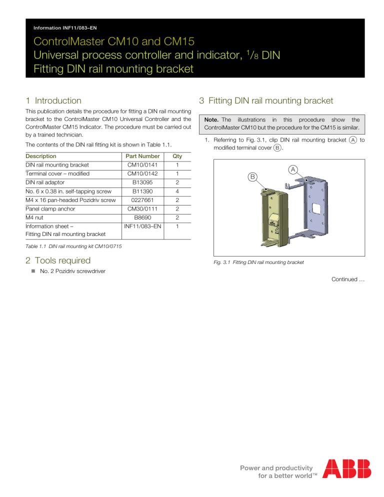
1. Referring to Fig. 3.1, clip DIN rail mounting bracket
A
to modified terminal cover
B
.
B
A
Fig. 3.1 Fitting DIN rail mounting bracket
Continued …
2. Referring to Fig. 3.2, secure DIN rail adaptors
C
to DIN rail mounting bracket using four x No.6 x 0.38 in. self-tapping screws
D
.
Note.
The inner holes enable the ControlMaster CM10 to be mounted vertically and the outer holes enable the
Controlmaster CM15 to be mounted horizontally.
3 Fitting DIN rail mounting bracket
5. Referring to Fig. 3.4, fit modified terminal cover, complete
with DIN rail mounting bracket assembly
G
, to the
ControlMaster ensuring clip
H
locates correctly in the terminal cover.
G
H
C
D
Fig. 3.2 Fitting DIN rail adaptors
3. Referring to Fig. 3.3, depress clip
E
and remove terminal cover
F
from the CM10 or CM15. Discard the terminal cover.
E
Fig. 3.4 Fitting DIN rail bracket assembly
a. Insert M4 nut
J
into the recess in panel clamp anchor
K and position anchor on top of the ControlMaster case as shown.
b. Secure panel clamp anchor
K
to DIN rail mounting bracket assembly using M4 x 16 pan-headed Pozidriv screw
L
.
c. Repeat steps a and b for second panel clamp anchor on the underside of the ControlMaster.
J
F
Fig. 3.3 Removing the rear terminal cover
4. Referring to Section 4 of the User Guide (CM10 –
IM/CM/B–EN or CM15 – IM/CM/I–EN) make connections to the rear terminals as required.
K
L
Fig. 3.5 Fitting panel clamp anchors
2 INF11/083–EN | ControlMaster CM10 and CM15 | Fitting DIN rail mounting bracket
Notes
Notes
ControlMaster CM10 and CM15 | Fitting DIN rail mounting bracket | INF11/083–EN 3
Contact us
ABB Limited
Process Automation
Howard Road
St. Neots
Cambridgeshire PE19 8EU
UK
Tel:+44 (0)1480 475321
Fax:+44 (0)1480 217948
ABB Inc.
Process Automation
125 E. County Line Road
Warminster
PA 18974
USA
Tel:+1 215 674 6000
Fax:+1 215 674 7183 www.abb.com
Note
We reserve the right to make technical changes or modify the contents of this document without prior notice. With regard to purchase orders, the agreed particulars shall prevail. ABB does not accept any responsibility whatsoever for potential errors or possible lack of information in this document.
We reserve all rights in this document and in the subject matter and illustrations contained therein. Any reproduction, disclosure to third parties or utilization of its contents in whole or in parts – is forbidden without prior written consent of ABB.
Copyright© 2011 ABB
All rights reserved
