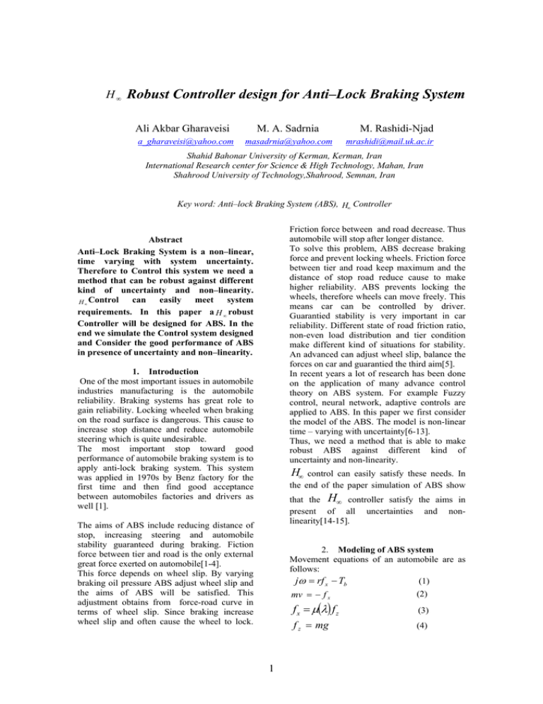
H Robust Controller design for Anti–Lock Braking System
advertisement

H∞ Robust Controller design for Anti–Lock Braking System Ali Akbar Gharaveisi a_gharaveisi@yahoo.com M. A. Sadrnia masadrnia@yahoo.com M. Rashidi-Njad mrashidi@mail.uk.ac.ir Shahid Bahonar University of Kerman, Kerman, Iran International Research center for Science & High Technology, Mahan, Iran Shahrood University of Technology,Shahrood, Semnan, Iran Key word: Anti–lock Braking System (ABS), H∞ Controller Friction force between and road decrease. Thus automobile will stop after longer distance. To solve this problem, ABS decrease braking force and prevent locking wheels. Friction force between tier and road keep maximum and the distance of stop road reduce cause to make higher reliability. ABS prevents locking the wheels, therefore wheels can move freely. This means car can be controlled by driver. Guarantied stability is very important in car reliability. Different state of road friction ratio, non-even load distribution and tier condition make different kind of situations for stability. An advanced can adjust wheel slip, balance the forces on car and guarantied the third aim[5]. In recent years a lot of research has been done on the application of many advance control theory on ABS system. For example Fuzzy control, neural network, adaptive controls are applied to ABS. In this paper we first consider the model of the ABS. The model is non-linear time – varying with uncertainty[6-13]. Thus, we need a method that is able to make robust ABS against different kind of uncertainty and non-linearity. Abstract Anti–Lock Braking System is a non–linear, time varying with system uncertainty. Therefore to Control this system we need a method that can be robust against different kind of uncertainty and non–linearity. can easily meet system H ∞ Control requirements. In this paper a H ∞ robust Controller will be designed for ABS. In the end we simulate the Control system designed and Consider the good performance of ABS in presence of uncertainty and non–linearity. 1. Introduction One of the most important issues in automobile industries manufacturing is the automobile reliability. Braking systems has great role to gain reliability. Locking wheeled when braking on the road surface is dangerous. This cause to increase stop distance and reduce automobile steering which is quite undesirable. The most important stop toward good performance of automobile braking system is to apply anti-lock braking system. This system was applied in 1970s by Benz factory for the first time and then find good acceptance between automobiles factories and drivers as well [1]. H∞ control can easily satisfy these needs. In the end of the paper simulation of ABS show that the H∞ controller satisfy the aims in present of all uncertainties and nonlinearity[14-15]. The aims of ABS include reducing distance of stop, increasing steering and automobile stability guaranteed during braking. Fiction force between tier and road is the only external great force exerted on automobile[1-4]. This force depends on wheel slip. By varying braking oil pressure ABS adjust wheel slip and the aims of ABS will be satisfied. This adjustment obtains from force-road curve in terms of wheel slip. Since braking increase wheel slip and often cause the wheel to lock. 2. Modeling of ABS system Movement equations of an automobile are as follows: (1) jω = rf x − Tb mv = − f x f x = µ(λ) f z f z = mg 1 (2) (3) (4) ′ x = [λTb P ] m is the automobile mass, v is the speed, ω is In which state vector is angular speed of wheel, f z vertical force, f x friction force of tier, Tb braking moment, r u = λα is the input of this nonlinear system. wheel radius and j wheel inertia. Wheel slipping can be found from the following: v − rω (5) λ= v For λ = 1 angular speed is zero i.e. wheel is locked and for λ = 0 i.e. v = rω and wheel is free. µ (λ ) is friction ratio of road-tier and is the nonlinear function and dependent to slip. The following figure shows this function. This function is related to vertical force ( f z ) , angular movement of steer (α ) , road surface, tier considering road condition and tier characteristics the peak of curve will change. and 3. H ∞ control theory The period of robust control back again to frequency domain thought in which H ∞ synthesis and robustness analysis of singular value is posed, H ∞ control is defined by Zames for the first time, and then structured singular value by Doyle was introduced these two are the key structure of the robust control [14]. Zames said that norm - ∞ is closer to application than norm–2. He claimed that LQG controllers were not succeed because of norm–2 minimization [15]. In H ∞ robust control design the frequency peak response of the closed –loop minimized such that frequency response curve is located under specific curve in which is the performance index of system behavior. Mathematically, H ∞ controller minimize norm ∞ for the worst model of the plant. Since the uncertainty of ABS system come from modeling error and internal parameter variation, H ∞ control can easily be robust against uncertainty and reduce its effect on output behavior. Consider figure [2] that d and n is disturbance and noise to the system respectively. Figure 1- Friction ratio of road-tier In this paper angular movement of steer is supposed to be zero. From (1), (2), (3), (4), (5) we have; r2 fz r (6) λ v = Tb − µ (λ ) j j Eq. (6) is nonlinear first order diff. Eq. That if β= r2 fz , r α= j j we have: λ v = − βµ (λ ) + α T b (7) That v have uncertainty. Breaking Eq. as follows: Figure 2- Closed-loop control together with noise and disturbance . Tb = P (8) One way of indicating stability margin in this system is to consider singular value to closed loop transfer function matrix from r to e, u and y . . T P + P = Ku u = λα − λ (9) S (s ) = (I + L(s )) (10) P is oil pressure, K and T are constant and λα is maximum curve slip µ (λ ) , R (s ) = F (s )(I + L (s )) (13) −1 T (s ) = L(s )(I + L(s )) from −1 L (s ) = G (s )F (s ) (7), (8). (9) and (10) the ABS system model is obtained: x = f ( x .u ) y=λ −1 S (s ) and T (s ) are . (14) (15) (16) called sensitivity and complementary sensitivity matrix respectively. There is no name for R (s ) . The plot of singular (11) (12) value matrix of S 2 (s ) , T (s ) and R(s ) play very important role in robust control design. In fact, S s is closed-loop function from d to y and to have small effect of disturbance on output we must have? (17) σ (S ( jw)) ≤ W1−1 ( jw) W2 = () F (s ) controller will be found with these weighting matrices. 5. Simulation ABS parameters are as follows: in order to reduce the effect of noise and uncertainty on the output we have: (18) σ (R( jw)) ≤ W2−1 ( jw) σ (T ( jw )) ≤ W 3− 1 ( jw ) r = .32 m , Fz = 4410 N , m = 450 kg λ d = 0.18 and j = 1kgm 2 , To search for robustness of H ∞ designed (19) controller we consider different situations: Ι) Linear system response without uncertainty : figure (4) shows sliding without uncertainty. We can see sliding can reach to 0.185 in less than 0.2 sec., which is very good. Fig (5) shows break moment, which can reach, to 1300 Newton in less than 0.2 sec. Π) Nonlinear system response without uncertainty: Fig (6) show non-linear system sliding that with small overshoot can reach to 0.183 in less than 0.2 second. Fig (7) show brake moment that with small overshoot reach to 1400 Newton. Ш) Non-linear system response with unmodeled dynamics uncertainty: Designed controller was applied to non-linear system with un-modeled dynamics. Fig (8) show that this controller is robust against this uncertainty and with sliding 0.18 can stop the car in 2.1 second. Fig (9) show that car can stop in 2.1 second with speed 20 m . Fig (10) shows that brake Figure 3- Generalized model of the plant From figure (3) and relationships (17), (18) and (19) to have small effect from noise, disturbance and uncertainty on output we have [15] T y1 u 1 ≤ 1 (20) in which: ⎡W S ⎤ T y1u1 = ⎢ 1 ⎥ ⎣W 3T ⎦ .005(s + 1) 0.525(1 + 2 s ) W3 = (1 + 0.05s ) (1 + 0.105s ) (21) and: s ⎡W1 − W1G ⎤ P ( s ) = ⎢⎢ 0 W 3 G ⎥⎥ ⎢⎣ 1 − G ⎥⎦ moment reach to 1400 Newton. ІV) Non-linear system response in snow road condition :Fig (11) shoes snow road that sliding is 0.19 and car can stop in 3.45 second Fig (12) indicate the rate of the speed slowness. V) Non-linear system response in icy-road condition: Fig (13) shows the sliding on icy road. Which is equal 0.19 and the car will stop in 4.1 second. Fig (14) indicates the rate of speed slowness of the car. (22) Therefore, getting W1 ,W2 and W3 which should satisfy the relationship (17),(18) and (19) P( s ) can be obtained. Having P (s ) , F ( s ) controller can be designed such that internal stability and condition(20) both were satisfied. H ∞ controller design for ABS system linear model is needed to design H ∞ controller. From non-linear system as follows: 4. A . X = AX + BU Y = CX + DU (23) (24) in which A is 3× 3 , B is 3× 1 , C is 1× 3 and D is zero. Weighting matrix W1 ,W2 and W3 are as follows: W1 = 10(s + 100 )(s + 20 ) (s + 15)(s + 7.5) Figure 4-Automobile sliding for linear model (25) 3 Figure 5- Automobile braking moment for linear model Figure 9- Automobile speed for nonlinear and uncertainty Figure 6- Automobile sliding for nonlinear model Figure 10- Braking Moment for nonlinear model with uncertainty Figure 7- Automobile Braking moment for nonlinear model Figure 11- Automobile sliding for non-linear model and Snow-road Figure 8- Automobile sliding for nonlinear model and uncertainty Figure 12- Automobile speed for nonlinear model and Snow-road 4 [7] Will A.B., Hui S. and Zak S.H., (1998),” Sliding Mode Wheel Slip Controller for an Anti-Lock Braking System, Int.J, of Vehicle Design,” Vol. 19, No.4, pp.523-539. [8] Christopher Edwards and Sarah K. Spurgeon, (1998),“Sliding Mode Control Theory and Applications,” Taylor & Francis Ltd. [9] George, F.M.Gerard, F.G. Yann , C,”Fuzzy Logic Continuous And Quantizing Control of An ABS Braking System, Sea Paper No.700377. [10] Layne, J.R, Kevin, Passino, M,Yurkovich, S. June (1993),”Fuzzy Learning Control for Antiskid Braking System, IEEE Tran on control system technology, Vol.1 No.2. [11] Sobottka c. and Singh T., September 1518, (1996),”Optimal Fuzzy Logic Control for Anti-Loc Braking System, Proceeding of the 1996 IEEE International Conference on Control Applications”, pp.49-54Dearborn, MI. [12] M., (1994),”Neural Network control of a Four-Wheel ABS Model, In Proceedings of the IEEE Midwest Symposium on Circuits and Systems”, Vol.2, No., pp. [13] YU J. S.,”A Robust adaptive Wheel-Slip Controller for Anti-Lock Brake System, Proceedings of the 36th CDC, pp.2545-2546, San Diego, CA, Dec. [14] Zames G. and Francis B.A., May (1983),”Feedback Minimax Sensetivity and Optimal Robusttness” IEEE Trans. ON AC I, AC-28, pp.585-601. [15] Francis B.A., (1987),”A Course in Figure 13- Automobile sliding for nonlinear model with icy-road Figure 14- Automobile speed for nonlinear model on icy-road 6. References [1] Drakunov S.,Ozguner U.,Dix P.,and Ashrafi B., Mar(1995),“ABS Control Using Optimum Search via Sliding Modes, IEEE transaction on Control System Technology”, vol.3, No., pp.79-85. [2] Jurgen R.k. (editor), (1995),”Braking Control, Chapter 15 of Auotomative Electronics Handbook, New York, McGraw Hill Inc". [3] Mack J. (editor), (1996),” ABS-TCS-VDC, Where will the Technology Lead Us, Society of Automotive Engineers”, Inc, PT-57. [4] Szostak, H,T, Allen, W.R, and Rosenthal,T.J. April (1988), ”Analytical Modeling of Driver Response in Crach Avoidance Maneuvering volume 2: An Interactive Model for Driver/Vehicle Simulation, U.S Department of Transportation Report”, NHTSA DOT HS-807-271. [5] Kawabe T, Nakazawa M, Nostu I, and watanabe Y, Des (1996),” A Sliding Mode Controller for Anti-Look Brake system: Usage of Sluggish Actuators, In Proceedings of the 35th Conference on Decision and Control” pp.2769-2770, Kobe, Japan. [6] Tahei S, and Nesari A. J. February 18-20, (1998),”A New Optimal Sliding Mode Nonlinear Control Strategy for Anti-Lock Braking Systems, Proceedings of the 17th IASTED International Con. On Modeling, Iden, and control”, pp,245-248, Grindelwald, Switzerland. H ∞ Control Theory, Springer-Verlag. 5


