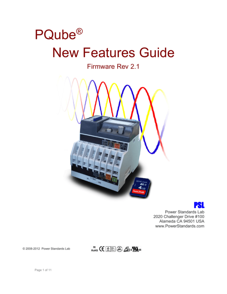
PQube®
New Features Guide
Firmware Rev 2.1
PSL
Power Standards Lab
2020 Challenger Drive #100
Alameda CA 94501 USA
www.PowerStandards.com
© 2008-2012 Power Standards Lab
Page 1 of 11
WARNING: Death, serious injury, or fire hazard could result from improper
connection or operation of this instrument. Carefully read and understand manual
before connecting this instrument.
AVERTISSEMENT: Si l'instrument est mal connecté, la mort, des blessures
graves, ou un danger d'incendie peuvent s'en suivre. Lisez attentivement le manuel
avant de connecter l'instrument.
WARNUNG: Der falsche Anschluß dieses Gerätes kann Tod, schwere
Verletzungen oder Feuer verursachen. Bevor Sie dieses Instrument anschließen,
müssen Sie die Anleitung lesen und verstanden haben.
ADVERTENCIA: Una conexión incorrecta de este instrumento puede producir la
muerte, lesiones graves y riesgo de incendio. Lea y entienda el manual antes de
conectar.
If this equipment is used in a manner not specified by the manufacturer, the protection provided
by the equipment may be impaired. Installation, service, and maintenance of your PQube must
only be done by an expert for electrical installations.
© 2008-2012 Power Standards Lab. All rights reserved. No parts of this document may be copied,
reproduced, or translated to another language without the prior written consent of Power
Standards Laboratory. “PQube” is a registered trademark of Power Standards Lab. “Windows”
“Excel”, and “PowerPoint” are registered trademarks of Microsoft Corporation.
The information contained in this document is subject to change without notice.
PSL MAKES NO WARRANTY OF ANY KIND WITH REGARD TO THIS MATERIAL, INCLUDING, BUT NOT
LIMITED TO, THE IMPLIED WARRANTIES OF MERCHANTABILITY AND FITNESS FOR A PARTICULAR
USE.
PSL shall not be liable for errors contained herein or for incidental or consequential damages in
connection with the furnishing, performance, or use of this material. If you do not accept this
limitation on liability, please return the product to PSL prior to use.
Produced in the United States of America.
Symbol
Meaning
Caution. Consult this manual in all cases where
this symbol is used.
Caution. Risk of electric shock
Alternating current
Alternating current (a.c.) or direct current (d.c.)
Double or Reinforced insulation
Functional earth terminal not relied on for safety
First Release: July 2012
Page 2 of 11
Table of Contents
Table of Contents
3
Trigger Temperature and Humidity Events .................................................................................. 4
Choose Which Types of Emails to Receive from your PQube....................................................... 7
Define Your Own Major-Dip Ride-Through Curve ........................................................................ 8
Support for Potential Transformers with Calibrated Ratios ....................................................... 11
Page 3 of 11
Trigger Temperature and Humidity Events
In Firmware 2.1, you can trigger temperature and humidity events with a TH1 probe. Each event
recording is complete with magnitude, duration, and timestamp. Specify upper and lower
thresholds for temperature and/or humidity.
Your PQube will send two email notifications:
1. When the temperature/humidity
first exceeds the threshold, your
PQube will send you a notification
for an Incomplete Event. It will
include the start time and the trigger
threshold.
Page 4 of 11
2. You will receive a second email when
the temperature/humidity comes
back within the threshold, plus
hysteresis. It will include the
timestamp, maximum or minimum
value during the event, and duration.
PQube Configurator Settings:
Setup.ini tags:
;---------------------------------------------------[External_Probe_Events]
;---------------------------------------------------; ------ Valid Values: ON, OFF
; ------ Set tags ON to enable event triggering on temperature and humidity on Probe 1 and
Probe 2.
; ------ Set thresholds for temperature in degrees C and humidity in percent.
Probe_1_Overtemperature_Event=ON
Probe_1_Undertemperature_Event=OFF
Probe_1_Undertemperature_Threshold_in_Deg_C=0
Probe_1_Overtemperature_Threshold_in_Deg_C=60
Probe_1_Temperature_Event_Hysteresis_in_Deg_C=2
; ------ Valid Values: ON, OFF
Probe_1_High_Humidity_Event=OFF
Probe_1_Low_Humidity_Event=OFF
Probe_1_Low_Humidity_Threshold_in_Percent_RH=0
Probe_1_High_Humidity_Threshold_in_Percent_RH=100
Probe_1_Humidity_Event_Hysteresis_in_Percent_RH=2
Page 5 of 11
You can also trigger the PQube’s relay output during a temperature or humidity event.
PQube Configurator Settings:
Setup.ini tags:
;----------------------------------------------------[Event_Relay_Trigger]
;----------------------------------------------------; Relays open for the event duration, or 3 seconds, whichever is longer.
; You can connect any event to any relay.
; One relay may be connected to multiple events;
; Any event can be connected to multiple relays.
; RLY1 is standard in every PQube. RLY2, RLY3, and RLY4 are factory-installed options.
; Examples: OFF means don't trigger a relay.
;
1 means trigger RLY1.
;
2 means trigger RLY2.
;
12 means trigger both RLY1 and RLY2.
Trigger_Relay_On_Dip=OFF
Trigger_Relay_On_Major_Dip=OFF
Trigger_Relay_On_Swell=OFF
Trigger_Relay_On_Interruption=OFF
.
.
.
Trigger_Relay_On_Probe_1_Undertemperature=OFF
Trigger_Relay_On_Probe_1_Overtemperature=1
Trigger_Relay_On_Probe_1_Low_Humidity=OFF
Trigger_Relay_On_Probe_1_High_Humidity=OFF
Trigger_Relay_On_Probe_2_Undertemperature=OFF
Trigger_Relay_On_Probe_2_Overtemperature=OFF
Trigger_Relay_On_Probe_2_Low_Humidity=OFF
Trigger_Relay_On_Probe_2_High_Humidity=OFF
Page 6 of 11
Choose Which Types of Emails to Receive from your
PQube
In previous versions of PQube firmware, your PQube sends you all types of emails (resets, events,
and trends).
In Firmware 2.1, you can choose which types of emails to receive from your PQube. This is useful if
you need to reduce network bandwidth. For example, you may want to enable emails for events
so you can respond to problems more quickly, and disable emails for trend reports (which may
include large attachments).
PQube Configurator Settings:
Setup.ini tags:
; ------ Enable these tags only if you do not want the PQube to automatically
;
send all emails. These tags will be ignored if Send_Email_On_Recording
;
is set to on, and the PQube will send all emails.
Send_Reset_Emails=OFF
Send_Events_Emails=ON
Send_Trends_Emails=OFF
Page 7 of 11
Define Your Own Major-Dip Ride-Through Curve
Sometimes you need to trigger a voltage sag based on magnitude and time. To do this, you can
define a ride-through curve which defines a specific set of voltage sags based on depth and
duration. Your PQube will trigger a Major Dip event if the voltage sag exceeds this curve.
For example, the SEMI F47 ride-through curve is commonly used in the semiconductor industry.
Equipment that complies with SEMI F47 requirements can withstand approximately 90% of all the
voltage sags in the world.
If your equipment is hit with a voltage sag that falls in the white region above the ride-through
curve (red line separating the white and blue sections of the graph), then your equipment should
be expected to “ride-through” the event and continue to operate normally without user
intervention. However, if your equipment is hit with a voltage sag that falls below the red line into
the blue region of the graph, then the voltage sag is classified as a “severe” event (or “Major Dip”)
and your equipment should not be required to withstand an event of this magnitude and duration.
The Major Dip event is useful for evaluating voltage dips based on magnitude and time. For
example, you will be notified of a voltage sag when the voltage dips below 90% remaining nominal
voltage for 1 or 2 cycles followed by a major sag when the voltage dip exceeds 90% for more than 1
second.
Because a voltage sag always precedes a major dip, your PQube will notify you of two events: a
Voltage Sag followed by a Major Sag. Therefore, voltage sag triggers must be enabled. Otherwise,
your PQube will not trigger a major sag. Specify up to 4 depth and duration points to define your
ride-through curve.
Page 8 of 11
PQube Configurator Settings:
TIPS:
Your regular Dip Threshold (default is 90%) must be equal to or higher than your Major Dip
Threshold settings. Otherwise, Major Dip will not be triggered.
Each subsequent Major Dip Threshold has to be lower than the previous one(s), and each
duration has to be shorter.
Page 9 of 11
Setup.ini tags:
; ------ Major dips are defined by your selected depth/duration curve. This is useful
;
for emulating PSL's PQ1 Power Quality Relay.
;
Valid values: OFF, ITIC, CBEMA, SEMI_F47, STANDARD, SAMSUNG_POWER_VACCINE,
;
MIL_STD_704E, MIL_STD_1399, CUSTOM
Major_Dip_Threshold_Settings=CUSTOM
; ------ This configuration is only valid if you set the Major_Dip_Threshold_Setting to CUSTOM
;
for the user to create their own custom threshold. Each additional threshold has to be
;
lower than the previous, and each duration has to be shorter.
;
Example of valid Usage
;
Major_Dip_Threshold_Level_1_in_Percent=80
;
Major_Dip_Threshold_Level_1_Duration_in_Seconds=5
;
Major_Dip_Threshold_Level_2_in_Percent=40
;
Major_Dip_Threshold_Level_2_Duration_in_Seconds=0.2
;
Example of invalid Usage
;
Major_Dip_Threshold_Level_1_in_Percent=40
;
Major_Dip_Threshold_Level_1_Duration_in_Seconds=2
;
Major_Dip_Threshold_Level_2_in_Percent=70
;
Major_Dip_Threshold_Level_2_Duration_in_Seconds=1
Major_Dip_Threshold_Level_1_in_Percent=87
Major_Dip_Threshold_Level_1_Duration_in_Seconds=2
Major_Dip_Threshold_Level_2_in_Percent=80
Major_Dip_Threshold_Level_2_Duration_in_Seconds=0.3
Major_Dip_Threshold_Level_3_in_Percent=60
Major_Dip_Threshold_Level_3_Duration_in_Seconds=0.1
Major_Dip_Threshold_Level_4_in_Percent=30
Major_Dip_Threshold_Level_4_Duration_in_Seconds=0.01
Page 10 of 11
Support for Potential Transformers with Calibrated
Ratios
You can now apply a gain correction factor for the mains voltage terminals, with a range of 0.95 to
1.05. Use with calibrated potential transformers to improve the accuracy of your measurements!
Example: Assuming a 10000:100 PT ratio, use the settings below:
Setup.ini tags
; ------ Valid values: from 1:1 up to 500000:1
;
You can use fractional values such as 1250.5:120
;
If your application requires a ratio higher than 10000:1
;
please contact factory for additional information
Potential_Transformer_Ratio=10000:100
; ------ Valid values: from 0.95 up to 1.05
L1_E_Voltage_Gain_Calibration_Factor=0.9995
L2_E_Voltage_Gain_Calibration_Factor=1.0251
L3_E_Voltage_Gain_Calibration_Factor=1.0087
N_E_Voltage_Gain_Calibration_Factor=1.0000
PQube Configurator Settings:
Visit http://www.powerstandards.com/PQube.php#firmware to get the latest
firmware!Need help? Contact us at support@powerstandards.com
Page 11 of 11

