Relay valve 973 0.. - inform.wabco
advertisement

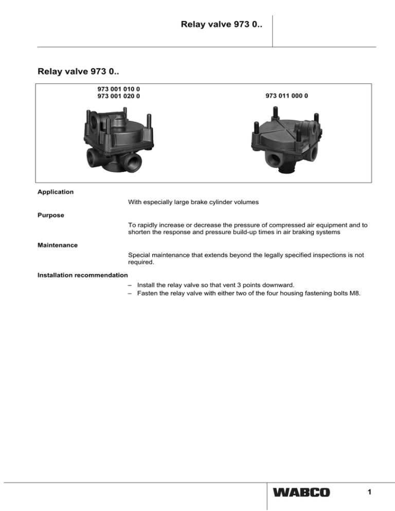
Relay valve 973 0.. Relay valve 973 0.. 973 001 010 0 973 001 020 0 973 011 000 0 Application With especially large brake cylinder volumes Purpose To rapidly increase or decrease the pressure of compressed air equipment and to shorten the response and pressure build-up times in air braking systems Maintenance Special maintenance that extends beyond the legally specified inspections is not required. Installation recommendation – Install the relay valve so that vent 3 points downward. – Fasten the relay valve with either two of the four housing fastening bolts M8. 1 Relay valve 973 0.. Installation dimensions 973 001 010 0 Connections 1 2 Energy supply 2 Energy delivery 3 Exhaust 4 Control port Relay valve 973 0.. Installation dimensions 973 011 000 0 Permissible installation position: ±90° Connections 1 Energy supply 2 Energy delivery 3 Exhaust 4 Control port Technical data Order number 973 001 010 0 973 001 020 0 973 011 000 0 Max. supply pressure 22 bar 13 bar Output pressure p2 8 bar 10 bar Control pressure p4 Port threads 8 bar (Max. operating pressure: 10 bar) M 22x1.5 - 14 deep Operating temperature range Weight 8 bar 10 bar 1 = M 22x1.5 - 14 deep 2, 4 = M 16x1.5 - 14 deep 1, 2 = M 22x1.5 - 13 deep 4 = M 16x1.5 - 12 deep -40 °C to +80 °C 1.1 kg 0.62 kg 3 Relay valve 973 0.. Pressure diagrams 973 001 010 0 973 001 020 0 973 011 000 0 Legend p2 Output pressure p4 Control pressure Operation When actuating the brake system the compressed air goes via port 4 into chamber A and moves piston (a) downward. This causes the outlet (c) to be closed and the inlet (b) to be opened. The air supply at port 1 now flows via chamber B and port 2 to the downstream brake cylinders. The pressure building up in chamber B acts on the undersides of the pistons (a). As soon as this pressure is slightly higher than the control pressure in chamber A, the piston (a) moves upward. Inlet (b) closes and the relay valve is in the neutral position. When the pressure in the pilot line is partially reduced, piston (a) is forced upwards once again, opening outlet (c), and the excess pressure at port 2 is evacuated 4 Relay valve 973 0.. through vent 3. If the actuating pressure at port 4 is fully evacuated, the pressure in chamber B pushes pistons (a) to their upper neutral position and the outlet (c) opens. The downstream brake cylinders are evacuated fully through vent 3. 5 Relay valve 973 0.. Overload protection Relay valve 973 011 201 0 Application Especially with drum-brake vehicles Purpose For the protection of the wheel brake from overload (added force) when service and parking brake are actuated simultaneously, Quick charge and venting of the spring brake cylinders (Tristop® cylinders). Trailer EBS E with PEM: The overload relay valve is already integrated in the pneumatic extension module (PEM). Installation dimensions 973 011 201 0 Permissible installation position: ±90° 6 Relay valve 973 0.. Technical data Order number 973 011 201 0 Max. supply pressure 12 bar Max. control pressure p41 / 42 10 bar 1 = M 22x1.5 (Mmax. = 53 Nm) M 16x1.5 (Mmax. = 34 Nm) Port threads Operating temperature range -40 °C to +80 °C Diagram 973 011 201 0 Legend p21 Output pressure p41/42 Control pressure 7 Relay valve 973 0.. Operation In driving position, chamber B is continuously supplied with compressed air through port 41 from the double release valve or PREV. The pressurized piston (b) keeps outlet (f) closed and through the depressed valve stem (c) keeps inlet (e) open. Port 21 receives the full pressure from the reservoir through port 1. After the check valve is open, the spring brake cylinders connected to port 21 are supplied with compressed air and the spring brakes are released. When using the service brake system the compressed air goes via port 42 in chamber A and pressurizes piston (a). Because of the counter-forces in chambers B and C, the pressure has no effect on the operation of the relay valve. Chamber B is fully evacuated by using the red pull button on the PREV or the double release valve. The released piston (b) is pushed up by the supply pressure in chamber C. Outlet (f) thereby opens, while inlet (e) is closed by the rising valve (c). The spring brake actuators are evacuated via outlet (f) and the exhaust 3. When in addition the service brake system is used, the compressed air goes via port 42 in chamber A and pressurizes piston (a). As chamber C is evacuated, this piston (a) goes down. Outlet (f) opens and inlet (e) opens. The compressed air pending at port 1 goes via chamber C and port 21 in the spring-type brake actuators. The spring brake is thereby released but only to the extent that the service brake pressure rises. Therefore, there is no compounding of the two braking forces. As soon as the pressure building up in chamber (C) becomes greater than the pressure present in chamber A, piston (b) goes up. Inlet (e) closes and the relay valve is in the neutral position. When the service brake is released (with parking brake still being actuated),chamber A is evacuated once again. The pressure in chamber C is greater, forcing piston (b) up. Outlet (f) opens and the spring brakes are connected with vent 3. 8