Grounding methods in mission critical facilities
advertisement

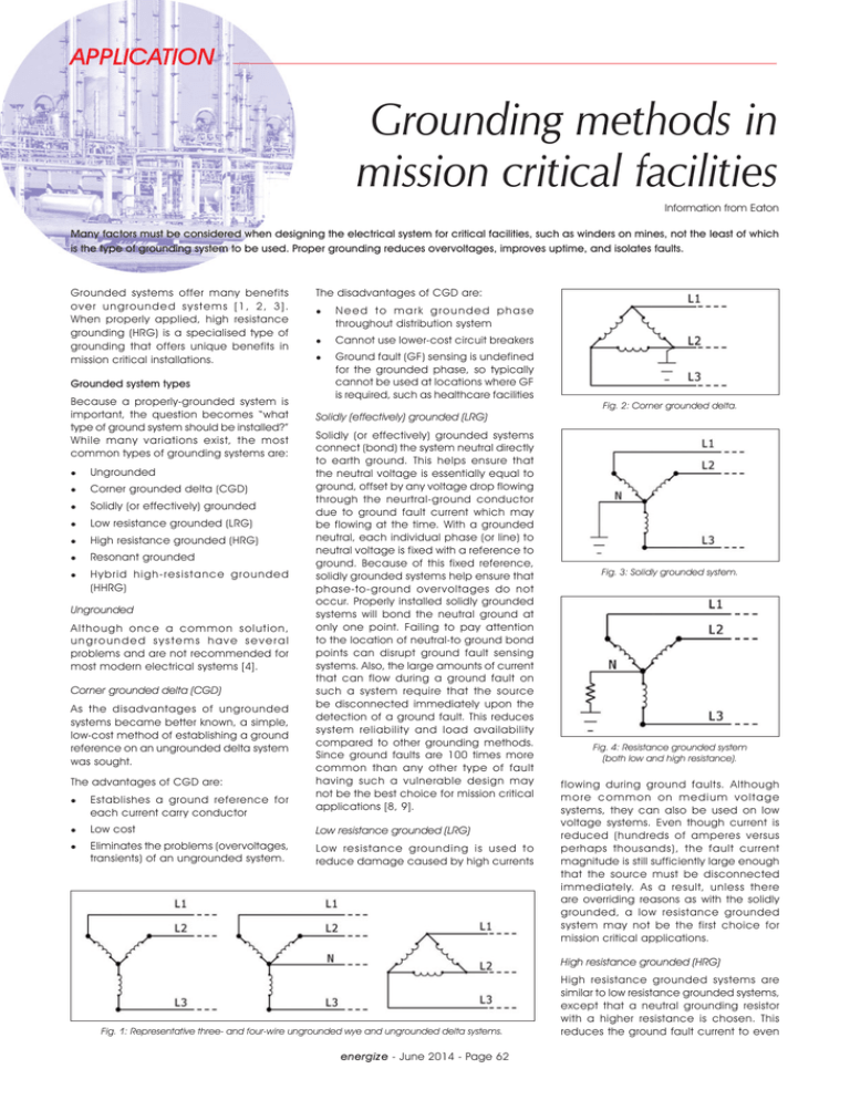
Grounding methods in mission critical facilities Information from Eaton Many factors must be considered when designing the electrical system for critical facilities, such as winders on mines, not the least of which is the type of grounding system to be used. Proper grounding reduces overvoltages, improves uptime, and isolates faults. Grounded systems offer many benefits over ungrounded systems [1, 2, 3]. When properly applied, high resistance grounding (HRG) is a specialised type of grounding that offers unique benefits in mission critical installations. Grounded system types Because a properly-grounded system is important, the question becomes “what type of ground system should be installed?” While many variations exist, the most common types of grounding systems are: Ungrounded Corner grounded delta (CGD) Solidly (or effectively) grounded Low resistance grounded (LRG) High resistance grounded (HRG) Resonant grounded Hybrid high-resistance grounded (HHRG) Ungrounded Although once a common solution, ungrounded systems have several problems and are not recommended for most modern electrical systems [4]. Corner grounded delta (CGD) As the disadvantages of ungrounded systems became better known, a simple, low-cost method of establishing a ground reference on an ungrounded delta system was sought. The advantages of CGD are: Establishes a ground reference for each current carry conductor The disadvantages of CGD are: Need to mark grounded phase throughout distribution system Cannot use lower-cost circuit breakers Ground fault (GF) sensing is undefined for the grounded phase, so typically cannot be used at locations where GF is required, such as healthcare facilities Solidly (effectively) grounded (LRG) Solidly (or effectively) grounded systems connect (bond) the system neutral directly to earth ground. This helps ensure that the neutral voltage is essentially equal to ground, offset by any voltage drop flowing through the neurtral-ground conductor due to ground fault current which may be flowing at the time. With a grounded neutral, each individual phase (or line) to neutral voltage is fixed with a reference to ground. Because of this fixed reference, solidly grounded systems help ensure that phase-to-ground over voltages do not occur. Properly installed solidly grounded systems will bond the neutral ground at only one point. Failing to pay attention to the location of neutral-to ground bond points can disrupt ground fault sensing systems. Also, the large amounts of current that can flow during a ground fault on such a system require that the source be disconnected immediately upon the detection of a ground fault. This reduces system reliability and load availability compared to other grounding methods. Since ground faults are 100 times more common than any other type of fault having such a vulnerable design may not be the best choice for mission critical applications [8, 9]. Low cost Low resistance grounded (LRG) Eliminates the problems (overvoltages, transients) of an ungrounded system. Low resistance grounding is used to reduce damage caused by high currents Fig. 2: Corner grounded delta. Fig. 3: Solidly grounded system. Fig. 4: Resistance grounded system (both low and high resistance). flowing during ground faults. Although more common on medium voltage systems, they can also be used on low voltage systems. Even though current is reduced (hundreds of amperes versus perhaps thousands), the fault current magnitude is still sufficiently large enough that the source must be disconnected immediately. As a result, unless there are overriding reasons as with the solidly grounded, a low resistance grounded system may not be the first choice for mission critical applications. High resistance grounded (HRG) Fig. 1: Representative three- and four-wire ungrounded wye and ungrounded delta systems. energize - June 2014 - Page 62 High resistance grounded systems are similar to low resistance grounded systems, except that a neutral grounding resistor with a higher resistance is chosen. This reduces the ground fault current to even APPLICATION Description Protection against overvoltages Operation during fault Ability to locate fault Ungrounded No Yes Limited1 Solidly grounded Yes No No Low resistance grounded Yes No No High resistance grounded Yes Yes Yes Table 1: Overvoltage and continuity benefits of brounding options. (Note 1: Loads can be selectively switched off while simultaneously monitoring voltage line to ground. When the feeder with the ground is switched off, the line to ground voltage jumps to a higher value. However, this is a very intrusive method of troubleshooting since it requires disconnecting loads.) Fig. 5: Resonant grounded system. Fig. 6: Hybrid high-resistance grounded system. Fig. 7: Grounding a phase in HRG system causes line-to-ground voltage to increase by √3. Note: Without a ground fault, the neutral-to-ground voltage is essentially zero. When a ground fault occurs, the neutral to ground voltage rises to equal the nominal line-to-neutral voltage. Fig. 8: Acceptable and unacceptable singlephase loads on HRG system per NEC/CEC. Fig. 9: Derived neutral using a wye-delta transformer. lower values, typically less than 10 A, and frequently less than 5 A on low voltage systems. Such small currents eliminate the need to trip immediately, allowing time to locate and clear the ground fault. Also, as will be discussed later, HRG systems can include features that assist in locating the ground fault, which speeds repairs and improves safety and reliability. Therefore, in certain applications, HRG systems are recommended for mission critical applications. One issue, however, is that while a ground remains in the system, the neutral voltage will rise to above ground potential. Some UPSs will view a neutral to ground voltage as a fault and inhibit transferring to and from bypass. For this reason, HRG systems may not be recommended for powering UPSs or other information and communication technology (ICT) loads. With an HRG system, the system designer will need to weigh the benefits of increased power availability into the UPS (due to GFs not causing a source trip) with the potential problems resulting when certain UPSs switch to bypass while a GF is present. Nevertheless, in all cases, HRG systems still can be configured to trip the upstream breaker, effectively mimicking a solidly grounded system while also providing the extra benefit of reduced arc flash incident energy releasing during a single GF event because the neutral resistance limits the GF current to very modest levels. While ground faults can occur anywhere, a somewhat more common location in data centers is within motors. The thinness of the winding insulation, the proximity of the winding to the stator, the high (and cycling) temperatures, and the (likewise cyclic) vibrations all stress the windings and create an environment conducive to ground faults. Having a grounding system like an HRG system would be desirable for mission critical applications. However, besides the UPS issue mentioned above, the United States National Electrical Code (NECT) and the Canadian Electrical Code (CEC) place additional restrictions on situations when HRG systems can be used. However, these restrictions tend to not apply to motor loads. In mission critical installations, larger motors are rarely connected line-to-neutral (one of the code prohibitions when using HRG). This means that mission critical sites energize - June 2014 - Page 63 could use HRG on the mechanical loads while using a solidly grounded system to power the ICT loads. Resonant grounded A less common grounding scheme is known as resonant grounding. Resonant grounded systems are grounded through a variable inductance called a Petersen coil. The coil is in series with the effective line-to-ground capacitance of each phase conductor and is tuned to produce an impedance based on the series LC circuit. Since the Petersen coil is adjusted based on what is connected at the time, the disadvantage of this design is that the Petersen coil would potentially need to be re-adjusted as different loads are switched on and off. Hybrid high-resistance grounded (HHRG) Hybrid high-resistance systems were developed for the special case of protecting generators from internal ground faults [5]. They operate as a low resistance grounded system with a bypass device closed under normal conditions. When a fault is detected, the bypass device opens and ground current is forced through a second, higher resistance value resistor. This reduces the current and also the likelihood of internal generator lamination damage. As shown in Table 1, only the HRG system provides protection against overvoltages, while also providing high service continuity and the ability to locate a fault—all attractive features for mission critical environments. HRG systems, however, must be installed per Article 250.36 of the NEC, which limits the use of HRG to only threephase installations where: No line-to-neutral loads are connected Ground detectors are installed • Only qualified persons ser vice the installation Continuity of service is required As mentioned earlier, this means that HRG systems cannot be used on threephase, four-wire systems where line-toneutral loads are connected. Since many commercial building distribution systems are three-phase, four-wire, loads are commonly connected between a line and neutral (e.g. 277 fluorescent lighting connected to a 480Y/277 three-phase, four-wire system). In such a system, the APPLICATION NEC would prohibit using an HRG system. The principal reason for the prohibition is that during a ground fault, the neutral conductor in an HRG system is no longer at ground potential. The line-to-ground voltage increases on the ungrounded phases to a value equal to the previous line-to-neutral voltage multiplied by √3. In some cases, this can stress overvoltage protective devices. Most likely, the NEC code-making panel did not want to verify if the myriad of electrical devices that might possibly connect to the neutral conductor could tolerate a raised voltage, so the code makes a blanket prohibition of the use of line-to-neutral loads on HRG systems. However, for three-phase, three-wire systems there are, by definition, no loads connected to neutral connections. In this case, HRG provides service continuity while simultaneously offering protection against transient overvoltages. the fault. This method, called a pulsing ground system, is one of the key features that differentiates the HRG system from all other grounding systems. A pulsing ground system works as follows: Source transformer – delta connected secondary Since a delta transformer winding has no neutral bushing, the recommended method of grounding a delta transformer is to first derive the neutral and then ground that derived neutral through a resistor. Since the maximum amount of neutral current is limited by the resistor chosen, the size of the transformer used to derive that neutral must only be large enough to provide the maximum fault current (typically 5 or 10 A) at the rated line-toneutral voltage (e.g. 277 V). The resistor is chosen to permit slightly more than system charging current to flow during a ground. Refer to [1] for a discussion of system charging current. For most low voltage systems, system charging current will be no more than 1 to 2 A. Source transformer – wye connected secondary Since a neutral bushing exists on a wye secondar y, adding HRG is as shown in Fig. 12. Fault location – pulsing grounding HRG systems, per the NEC, must include a method for detecting the presence of a ground fault. However, HRG systems can also be provided with an optional but recommended feature that helps locate Operator switches the HRG system into “pulse” mode to begin the fault locating process Fig. 10: Derived neutral using a wye-broken delta transformer. HRG activates a timer that selectively shorts out part of the grounding resistor Ground current increases to roughly twice the original value (e.g. 5 to 10 A) After 1 to 2 seconds, the HRG timer times out and the resistor bypass is removed Fig. 11: Derived neutral using a zig-zag transformer. Ground current then decreases (e.g., 10 A to 5 A) Process repeats to “a” until operator locates fault (step 3) and switches system out of pulse mode Installing HRG systems HRG can be installed either as part of a new installation or as a retrofit. HRG solutions can also be installed on systems fed by either wye or delta transformer secondaries. Note that regardless of the type of connection, all HRG systems must have ground detectors per NEC 250.36. For this reason, manufacturers typically package the grounding resistor and detection systems into a single, easy-toinstall package. Once a fault is detected, an alarm is triggered (e.g., contact closure to PLC, DCS, BMS, horn, light) Operator places a clamp-on ammeter over all current-carrying conductors (even if enclosed in conduit) starting from the source out to each load. If the ammeter is clamped between the source and the fault, the pulsing will be visible. Fig. 12: HRG with wye connected secondary. If the ammeter is clamped on a feeder without a ground fault, pulsing will not be visible. A clamp-on ammeter with a sufficiently large current transformer (CT) window diameter to fit over any conduit can be used to detect this pulsing current. In the case of a ground fault, the current flowing through the conductors will not sum to zero; this difference will be displayed on the meter. Since the current is very low (about 5 A), the pulsing system makes the ground current more visible against ordinary background current that might be displayed due to position of the CT relative to other current carrying conductors. The “heartbeat” pulse stands out from other noise signals that might be present. Fig. 13: Clamp on ammeter can be used to detect location of a fault. For more information on pulsing ground detection systems, refer to references [6] and [7]. Multiple sources/multiple grounds As discussed earlier, the NEC/CEC require a ground fault detection system on all HRG systems. Multiple sources (especially those that can be paralleled, such as M-T-M systems) and systems with multiple ground sources complicate ground fault sensing [11]. Eaton’s Consulting Application Guide (CAG) describe various schemes for detecting the location of ground faults in systems with multiple sources (Figs. 15 and 16). Those sources may or may not be grounded. However, one type of system requiring extra scrutiny energize - June 2014 - Page 64 Fig. 14: Power Xpert snapshot of ground current waveform “heartbeat” after HRG “pulsing” is activated. is a system with multiple sources, each separately grounded and each paralleled to another. For such a system, a DGFS is recommended. Differential ground fault system (DGFS) A DGFS system uses signals from multiple sensors and connects those sensors in a differential or bridge scheme. The purpose APPLICATION Fig. 15. Dual source system – single point grounding. of the differential connection is to measure the difference of current flowing into or out of a zone and only trip when the fault exists within that zone [11]. [5] References [1] [2] [3] [4] IEEE 142-2007: “IEEE Recommended Practice for Grounding of Industrial and Commercial Power Systems”. IEEE 1100-2005: “IEEE Recommended Practice for Powering and Grounding Electronic Equipment”. D Shipp and F Angelini: “Characteristics of different power system neutral grounding techniques: fact and fiction,” 1988. DG Loucks: “Transient Overvoltages on Ungrounded Systems from Intermittent Ground Faults”, www.eaton.com/ecm/ [6] [7] Fig. 16. Dual source system – multiple point grounding. groups/public/@pub/@electrical/ documents/content/ia08700001e.pdf D Shipp, et.al: “Switching Transient Analysis and Specifications For Practical Hybrid High Resistance Grounded Generator Applications”, 2009, www.eaton.com/ ecm/groups/public/@pub/@electrical/ documents/content/ct_237872.pdf Eaton High Resistance Grounding Overview: www.eaton.com/ecm/groups/public/@ pub/@electrical/documents/content/ br01905001e.pdf Eaton Resistance Grounding Systems: www.eaton.com/Electrical/Consultants/ ConsultingApplicationGuide/ idcplg?IdcService=GET_FILE&RevisionSele ctionMethod=LatestReleased&Rendition =Primary&dDocName=TB02203002E [8] Eaton: “Fault Characteristics in Electrical Equipment,” www.eaton.com/ecm/groups/ public/@pub/@electrical/documents/ content/tp08700001e.pdf [9] IEEE 493-1997: “IEEE Power Systems Reliability” [10] DG Loucks: “3-Pole and 4-Pole Transfer Switch Switching Characteristics”, www. eaton.com/ecm/groups/public/@ pub/@electrical/documents/content/ ia08700002e.pdf [11] Eaton: “Ground Fault Isolation with Loads Fed from Separately Derived Grounded Sources”, http://pps2.com/go/dgfs/ Contact Marlene Coetzee, Eaton, Tel 011 824-7400, marlenecoetzee@eaton.com Welcome to the future – a future of Mwangaza We are all writing a part of the script which tomorrow’s society will play out. At Royal HaskoningDHV we would like the title to read: ‘Welcome to the future’ - and for our chapter in that script to read ‘Mwangaza’ - a Swahili word which means ‘light’. Together with our partners and clients we consider how we can create a welcoming future - developing efficient and smart living. Whether switching on a light, travelling to work or drinking a clean glass of water - the solutions and work of our engineers surround us, making lives better and brighter. Our work contributes to the sustainable development of communities. Together, we deliver innovative sustainable answers to today’s challenges. Royal HaskoningDHV is an independent, international engineering and project management consultancy. energize - June 2014 - Page 65 royalhaskoningdhv.com/za


