α-MAX Electric Actuators types ER 20-45-60-100
Installation and operating instructions
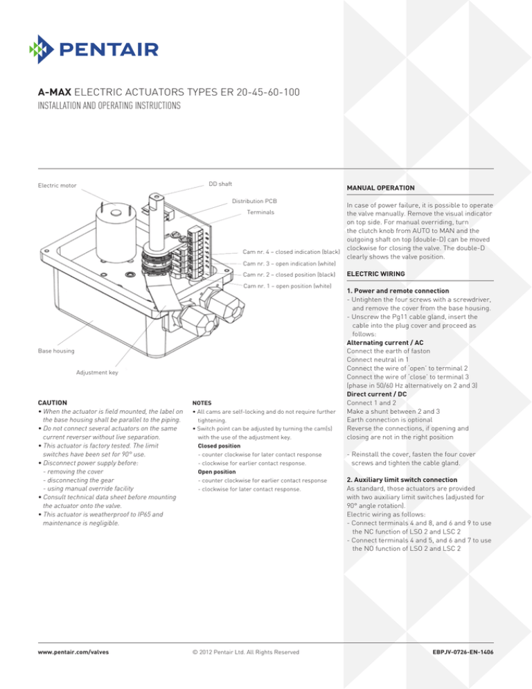
Electric motor
DD shaft
Manual operation
Distribution PCB
In case of power failure, it is possible to operate
the valve manually. Remove the visual indicator
on top side. For manual overriding, turn
the clutch knob from AUTO to MAN and the
outgoing shaft on top (double-D) can be moved
clockwise for closing the valve. The double-D
Cam nr. 4 – closed indication (black)
clearly shows the valve position.
Terminals
Cam nr. 3 – open indication (white)
Cam nr. 2 – closed position (black)
Cam nr. 1 – open position (white)
Base housing
Adjustment key
CAUTION
• When the actuator is field mounted, the label on
the base housing shall be parallel to the piping.
• Do not connect several actuators on the same
current reverser without live separation.
• This actuator is factory tested. The limit
switches have been set for 90° use.
• Disconnect power supply before:
- removing the cover
- disconnecting the gear
- using manual override facility
• Consult technical data sheet before mounting
the actuator onto the valve.
• This actuator is weatherproof to IP65 and
maintenance is negligible.
Notes
• All cams are self-locking and do not require further
tightening.
• Switch point can be adjusted by turning the cam(s)
with the use of the adjustment key.
Closed position
- counter clockwise for later contact response
- clockwise for earlier contact response.
Open position
- counter clockwise for earlier contact response
- clockwise for later contact response.
www.pentair.com/valves
© 2012 Pentair Ltd. All Rights Reserved
Electric Wiring
1. Power and remote connection
- Untighten the four screws with a screwdriver,
and remove the cover from the base housing.
- Unscrew the Pg11 cable gland, insert the
cable into the plug cover and proceed as
follows:
Alternating current / AC
Connect the earth of faston
Connect neutral in 1
Connect the wire of ‘open’ to terminal 2
Connect the wire of ‘close’ to terminal 3
(phase in 50/60 Hz alternatively on 2 and 3)
Direct current / DC
Connect 1 and 2
Make a shunt between 2 and 3
Earth connection is optional
Reverse the connections, if opening and
closing are not in the right position
- Reinstall the cover, fasten the four cover
screws and tighten the cable gland.
2. Auxiliary limit switch connection
As standard, those actuators are provided
with two auxiliary limit switches (adjusted for
90° angle rotation).
Electric wiring as follows:
- Connect terminals 4 and 8, and 6 and 9 to use
the NC function of LSO 2 and LSC 2
- Connect terminals 4 and 5, and 6 and 7 to use
the NO function of LSO 2 and LSC 2
EBPJV-0726-EN-1406
α-MAX Electric Actuators types ER 20-45-60-100
Installation and operating instructions
Wiring diagrams
Notes
LSO 1
LSC 1
LSO 2
LSC 2
C
M
H
Th
P
RM
Model TVC-ER with 240 V AC
Open
Close
= Open travel
= Close travel
= Open indication
= Close indication
= Capacitor
= Electro motor
= Heating element
= Thermostat
= Potentiometer
= Motor control
Optional
Model TVC-ER with 100-240 V AC multi-voltage
N
T
Open
1
2
LSO 1
Close
3
LSC 1
4
5
LSO 2
6
7
17
18
20
-
19
+
21
LSC 2
P
RM
EBS 24
Optional
Model TVC-ER with 24 V DC motor
Open
Customer
Close
Shunt
Pentair
2
α-MAX Electric Actuators types ER 20-45-60-100
Installation and operating instructions
Security enclosure for fail-safe action
Ph
N
Switch 1
Supply: 230V 50/60 Hz
1
2
Relay 2
EBR
Relay 1
EBR
0
4
5
6
1
2
3
230V 50HZ
Electric
Actuator 1
*
7
3
Security Enclosure
EBT 1/230
Type ER 20-45-60-100
Switch 2
Notes
1. As standard, this enclosure comes with single
relay EBR. Second relay is optional.
2. Before charging, reconnect the red wire of the
battery. During charging, LED (yellow) lights up.
Total charging time is 48 hours.
3.If battery is not fully charged at first usage,
LED (red) will light up during ± 2 minutes.
4.In case of supply failure, LED (green) lights up.
5.The NiCd battery shall be handled in accordance
with the local regulations.
6. Battery life is shortened by 50% for every 10°C
above an ambient temperature of 25°C
0
8
9
10
1
2
3
230V 50HZ
Electric
Actuator 2
Parts list type ER 20-45-60-100
Item
Description
1
Visual position indicator (or handle)
2
ABS cover
3
SS screws (4)
4
Circuit board for power distribution
5
Card support
6
Gear box plate
7
Shaft output gear
8
Gland Pg11 – IP67
9
Housing nylon GF6.6
10
Gear train assembly
11
Bearing
12
Cams (4)
13
Motor
* Handle only available for ER-20
3


