Experiment 5b: Delta-Wye transformer
A delta-wye configuration is typically used to step down transmission
line and distribution line voltages. For example, it may be used to step
down a 13.2KV distribution line voltage to a 240V/120V single-phase
residential supply or a 208V/120V Three-phase commercial supply. A
four wire service can provide Three phases of 208V line to line voltage
and three phases of 120V line to neutral voltage.
Equipment and Parts
Function Generator, Oscilloscope, DMM, and Breadboard.
Resistors: Three 10Ω, three 1k, all ¼ watt, 5%.
Capacitor: 0.68uF, 5%, Film type (4.7µF ceramic for 60Hz).
Transformer, Three 500Ω CT to 500Ω CT, 400mW (see appendix 2).
Recommended: ZICON 42TU500-RC (from Mouser Electronics)
Note: The specified 400mW transformer may be used at 60Hz. If 60Hz is
used, use a 4.7µF capacitor instead of the 0.68µF. The results will show a
somewhat lower efficiency.
Procedure: Part 1, No Fault
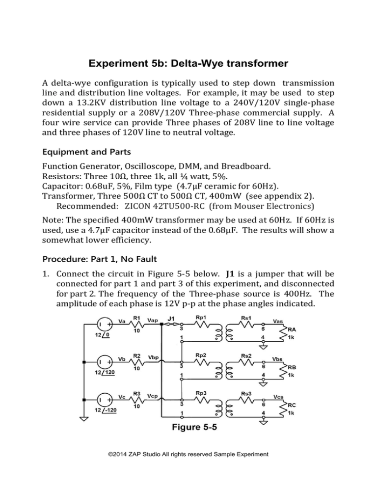
1. Connect the circuit in Figure 5-5 below. J1 is a jumper that will be
connected for part 1 and part 3 of this experiment, and disconnected
for part 2. The frequency of the Three-phase source is 400Hz. The
amplitude of each phase is 12V p-p at the phase angles indicated.
©2014 ZAP Studio All rights reserved Sample Experiment
2. Connect oscilloscope channel 1 to Va. Trigger on channel 1. Va will
be the reference phase for the entire experiment.
3. Measure and record the magnitude of Va and the magnitude and
phase angle of Vb.
Va:________ V p-p
θa: 00
Vb:________ V p-p
θb:_______0
Connect channel 2 of the oscilloscope to P2. Measure and record the
magnitude of Vc and the magnitude and phase angle of Vc.
Vc:________ V p-p
θc:_______0
4. Measure and record the primary voltages Vap, Vbp, and Vcp.
node
Vap
Vbp
Vcp
Mag. V p-p
Angle Deg.
5. Measure and record the secondary voltages Vas, Vbs, and Vcs.
node
Vas
Vbs
Vcs
Mag. V p-p
Angle Deg.
Procedure: Part 2, Open Primary Winding
1. Remove the jumper J1.
2. Measure and record the primary voltages Vap, Vbp, and Vcp.
node
Vap
Vbp
Vcp
Mag. V p-p
Angle Deg.
©2014 ZAP Studio All rights reserved Sample Experiment
3. Measure and record the secondary voltages Vas, Vbs, and Vcs.
node
Vas
Vbs
Vcs
Mag. V p-p
Angle Deg.
Procedure: Part 3, Reactive Load
1. Reconnect the jumper J1. Connect a 0.68µF capacitor across Rc
(4.7µF for 60Hz) .
2. Measure and record the primary voltages Vap, Vbp, and Vcp.
node
Vap
Vbp
Vcp
Mag. V p-p
Angle Deg.
3. Measure and record the secondary voltages Vas, Vbs, and Vcs.
node
Vas
Vbs
Vcs
Mag. V p-p
Angle Deg.
Analysis, Part 1
Use the part 1 measurements to make the calculations below.
1. Calculate the primary currents, Ia, Ib, and Ic.
2. Calculate the secondary line to line voltages and the total power, P,
delivered to the load.
3. Calculate the total complex power, S, and total average power, P.
Calculate the circuit’s power factor.
4. Calculate the efficiency of the circuit and of the 3-phase transformer.
5. Compare your results to a simulation.
©2014 ZAP Studio All rights reserved Sample Experiment
Analysis, Part 2
Use the part 2 measurements to make the calculations below.
1. Calculate the primary currents, Ia, Ib, and Ic.
2. Calculate the secondary line to line voltages and the total power, P,
delivered to the load. Calculate the efficiency of the circuit.
3. Calculate the total complex power, S, and total average power, P.
Calculate the circuit’s power factor.
4. Explain the voltage across the load resistor, Ra, when the primary
winding of the phase a is open (R1 removed).
Analysis, Part 3
Use the part 3 measurements to make the calculations below.
1. Calculate the primary currents, Ia, Ib, and Ic.
2. Calculate the secondary line to line voltages and the total power, P,
delivered to the load.
3. Calculate the total complex power, S, and total average power, P.
Calculate the circuit’s power factor.
4. Compare your results to a simulation.
LTspice Simulation
©2014 ZAP Studio All rights reserved Sample Experiment


